2018年11月29日星期四

What is a modulator or modulation? What’s the types of modulation?

What is a modulator?
Unless you’re in a commercial building or a hotel, you probably don’t think about modulators. In fact if you think of them at all you probably think back to your old game system. You used a device back then called an “RF Modulator” that put the output from the game system on channel 3. This was sort of mandatory if your TV didn’t have A/V inputs and a lot of them back then didn’t.
Modulators are still around but they’ve grown up and gotten a lot fancier.
What is modulation?
In order to understand what a modulator is, you have to understand what it does. A modulator, well, modulates. When you look at an unaltered video and audio signal, it travels through a wire in such a way that nothing else can travel on that wire. We call this baseband video. Modulation is a trick that takes this signal and only lets it occupy a portion of the “space” on a wire.
HDMI Encoder Modulator,16in1 Digital Headend,HD RF Modulator at Soukacatv.com
Let’s dig in a little further.
Modulation is a trick that lets you put more than one signal on a wire or over the air. Without it there would only be one TV station. The problem is that even with the best diagrams, it’s hard to explain. The best way I can think of is if you think about music. When you hear a song you’re taking in the whole song, but if you have a trained ear you can listen to just the drums or just the vocals. If you concentrate hard enough you can mentally block out everything else. Now, if you were a robot you could concentrate so well that nothing else would even enter your mind.
In essence, that’s modulation. We take a bunch of different signals and we do something special to each one of them, something that makes it stand out. If we go back to the song analogy, one would be the sound of the drums. One would be the sound of the lead guitar. One would be the lead singer.
Different kinds of modulation
When you’re talking about modulating a video or audio signal it’s done using a carrier. We take the basic signal and we mathematically add it or subtract it to a much more basic signal. This way the whole signal stays intact and you can have as many different signals as you have carriers. Each one doesn’t interfere with the others because they are all on different carriers.
Two of the easiest forms of modulation are amplitude modulation and frequency modulation. With amplitude modulation (AM) you make the carrier wave taller or shorter to add a signal to it. With frequency modulation (FM) you make the wave slower or faster to add a signal to it. This is pretty easy to visualize, thanks to this gif from Wikipedia.
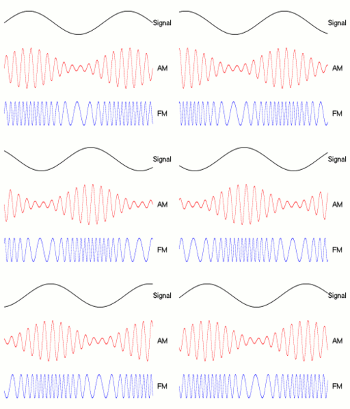
250px-Amfm3-en-de
Unfortunately AM and FM, as easy as they for humans to understand, aren’t really that efficient. When you need to get a lot of really large signals onto a wire, you need to use quadrature amplitude modulation (QAM) which uses two carrier waves and the kind of math that normal humans don’t have a chance of understanding. It all gets visualized in sort of a constellation that looks like this, (again, thanks Wikipedia.)
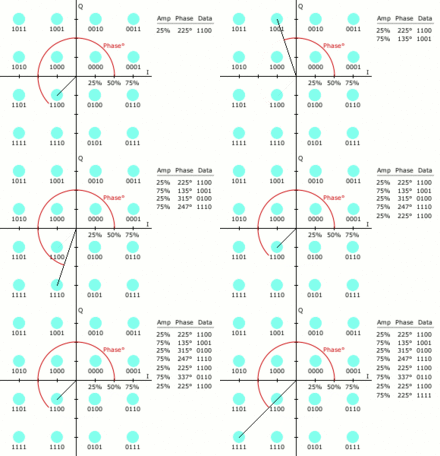
220px-QAM16_Demonstration
This constellation can represent any combination of numbers from 1 to 16 which is enough to carry about a fourth of the information needed for a full video and audio signal.
What’s the real world use of a modulator?
Modulators are used in the real world to place multiple audio and video streams on the same wire. This is done to make it easier to get them from one point to another. For example a hotel would use modulators to put the output from 32 satellite TV boxes on one wire so it’s easy for you to choose the channel you want from your room. Each signal has its own modulator, and each signal ends up taking a small bit of space on a single cable. In this way you can have several hundred channels on one cable if you wanted.
You can’t talk about modulators without…
…talking about encoders. Generally a modulator and encoder are built into the same box. The modulator is the part that puts the signal on the wire, but generally in order to get to that point it first must be encoded.
If you were to look at a pure, uncompressed HD signal it would take up about 2.2 gigabytes per second. That’s a humongous amount of space and you wouldn’t be able to modulate it very effectively. If you’re going to fit 100 or more channels on a wire you need each one to be about 6-10 megabits per second or smaller. That’s where encoders come in.
An encoder uses extremely fancy math to take the important parts of a signal and compress them down. The unimportant parts, like details you would never see, are discarded. In this way the signal can be compressed small enough that it fits where you need it to fit, and the modulator can do its work.
The best thing about modulators and encoders
You don’t really need to understand the extremely complex math involved in compressing and tailoring a signal and then placing it within a predefined frequency range to know that it works. The important thing is that it does work. Generally speaking you connect your video and audio signal to a modulator/encoder, you say what channel you want it to end up on, and it just works. Then, you combine the outputs of all the modulators onto one wire. If each modulator uses a different channel then none of them interfere with each other. At the other end, the viewer chooses a channel, and the TV demodulates and decodes the signal, then displays it.
Established in 2000, the Soukacatv.com (DSW) main products are modulators both in digital modulators and analog modulators, amplifier and combiner. We are the leading communication supplier in manufacturing the headend system in China. Our 16 in 1 and 24 in 1 now are the most popular products all over the world. For more, please access to https://www.soukacatv.com/.
Source: solidsignal.com

2018年11月27日星期二

What Is an RF Modulator Used For? The Application of RF Modulators | Soukacatv.com

Outmoded home electronics still have a lot of entertainment potential, from vintage video game systems and VCRs, to elderly television sets. Getting them to work together can be an interesting exercise in nostalgia, often requiring the use of oddball pieces of equipment such as RFmodulators. These were common in the 1980s and early 1990s, permitting the use of newer technology with older television sets.

The Back of the Set
Modern televisions can accept signals from a large number of differing types of equipment, but older sets are much simpler. Most have only one or two types of simple inputs. The oldest models have a pair of screw terminals, designed to accept the 300-ohm signal from an external antenna. Televisions from the 1970s and 1980s typically added a round, threaded 75-ohm connection known as an "F-connector," though most consumers know it simply as a cable-TV connection. As new forms of electronics came onto the market, those basic connections quickly became outmoded.

A/V Connections
Newer devices, such as VCRs and the early video game systems, began to separate out the audio and video signals for better sound and picture quality. If your TV set had the corresponding inputs, you could connect them with a simple patch cord. However, if all you had was a cable connection or antenna terminals, you needed an additional piece of equipment to help the device communicate with the TV. This device, the RF modulator, combined the audio and video signals back together in a form your TV could accept.
Using an RF Modulator
Although the product has mostly disappeared from the marketplace, used RF modulators are still widely available online, and can be found at thrift stores and yard sales. Typically, they provide a set of audio/video inputs for your game system or DVD player, and newer versions might also include an S-video input. The output is a short piece of cable with an F-connector, designed to screw to the back of your TV. Slide the switch on your RF modulator to either the channel 3 or channel 4 setting, then turn on your TV and tune it to that channel. You should see the signal from your video game, camcorder, VCR or DVD player.
A Few Extra Adaptors
Depending on the equipment you connect, you might need a few extra adaptors. For example, if your TV has only screw terminals for an antenna, you'll need a small "pigtail" adaptor that screws into the RF modulator's F-connector and provides screw connectors at the other end. Most RF modulators only have one input for audio, so if your source provides left and right stereo signals you'll need a Y-adaptor to combine them into one connection.
Established in 2000, the Soukacatv.com (DSW) main products are modulators both in digital modulators and analog modulators, amplifier and combiner. We are the leading communication supplier in manufacturing the headend system in China. Our 16 in 1 and 24 in 1 now are the most popular products all over the world. For more, please access to https://www.soukacatv.com/.

Source: techwalla


2018年11月26日星期一

How Does Signal Modulation Work? | soukacatv.com


To understand how wireless data transfer happens, we need to understand:
• What is frequency?
• Message / Data Signals
• time representation
• frequency representation, and why is it important?
• How do filters work?
• FCC Communication bands
Modulation and demodulation
You can spend years at University learning these subjects in depth (or on Wikipedia, if that’s your style!). This is designed to be a flash flood of knowledge. This was originally put together as a PowerPoint for non-EE students in my senior project group who were curious about our lingo when we talk about “900 MHz” or “2.4 GHz” or “Frequency Hopping”. As such, it is not complete, thorough, and skips many details that one would include in a professional analysis of a system. This is only to provide a concept of wireless transmission.
What is Frequency?
Frequency is the unit describing how often something oscillates, or goes back and forth. Units are Hertz (Hz), or the inverse of a second. Something oscillating 60 times per second has frequency 60 Hz. For our purposes, we are going to focus on audio waves (oscillation of air pressure) and how it gets broadcasted from a radio station to your car in the range of hundreds of kilohertz (or any AM radio station). Any wave has a frequency – light, for example. Generally light and other higher frequency waves (e.g. x-rays, gamma rays, microwaves) are represented by their wavelength, not frequency. For example, green light is around 400 nanometers. Here is a picture showing the relationship of units on a traveling wave:Basic units of a sine wave.

Assuming constant speed of the signal, wavelength and frequency are interchangeable. That is outside the scope of this article, though.

Message Signals of Varying Complexity
Sending a signal that is a pure sine wave is called a “tone”. It carries no real information, and doesn’t sound that great either. Here is an image of a sine wave, with time on the X axis and voltage on the Y axis. This is 150 Hz for reference.


Single tone signal (time domain)
Okay, so why am I showing you this? Let’s take a look at increasingly complex signals in the time domain. Here is a two tone signal (two tones, added together). It is the same sine wave above, added together with another sine wave with twice the frequency, 300 Hz.


Dual tone signal (time domain)

How about a signal composed of many tones of varying frequencies:

Multi-tone signal (time domain)
It’s starting to get a bit hairy. The only real information you can gather from that is voltage level at a specified time. That’s the essence of a message, and extremely important – but makes for difficult analysis, and even more difficult for understanding the way modulation works. This is why you may want to use a different way of graphing a signal: the frequency domain. It is a representation of how strong the signal is over a range of frequencies. Let’s look.
Why is the Frequency Spectrum of a Signal Important?
There is a precise mathematical operation to convert a chunk of a signal into the frequency domain. It is dense, difficult, and takes practice to master. I even struggle with convolution of non-trivial signals regularly. Regardless, let’s see what our three signals above look like in this representation (skipping to the solution). Instead of plotting a signal’s voltage in time, we are plotting the power of the signal by frequency.

Single tone signal (frequency domain)

Dual tone signal (frequency domain)

Multi-tone signal (frequency domain)
Notice the clear spikes? That is the mathematical representation of a sine wave at that particular frequency (X-axis). Ideally, these spikes would be infinitely narrow (width) and infinitely tall, but due the techniques used by my Spice software, it is imperfect. This is called an impulse signal. Read more on this here! For the tone, we see one spike at 150 Hz. The dual tone has two spikes, 150 Hz and 300 Hz. The multi-tone signal that was unreadable in the time domain has been clearly chopped into small spikes, representing all the frequencies that were summed to create the signal.
A final example would be to show an audio signal. In the below picture, I have taken a 15 second sample of the song “White Room” by Cream. Don’t worry, no microphones were damaged during Eric Clapton’s guitar solo!

Audio Signal
This is how most signals appear, especially analog ones. The human voice and instruments do not play as discreet frequencies, and thus there is frequency content over an entire range (even though some of that content is almost inaudible). This range is taken from 3 Hz to 20 kHz, the approximate range of the human ear. Bass notes are lower in the range, while treble is higher. The Y-scale is represented in dB, which is a unitless representation of proportion. In essence, the higher the dB value, the more of that frequency is in the signal.
In theory, we can represent this analog signal as the sum of an infinite number of tones added together.
Filters!
Hopefully the graphical representation of frequency domains will shed some light on filter design. There are four types of filters:
• Low Pass filter: all frequencies over the “cutoff” are removed.
• High Pass filter: all frequencies under the “cutoff” are removed.
• Band Pass filter: All frequencies outside a distance from the “center” are removed.
• Band Stop filter: All frequencies within a distance from the “center” are removed.

Clockwise: Band Pass, High Pass, Low Pass filters
The “3dB” point is where signal output is reduced by ~30%. It has to do with how “log” magnitude is calculated (dB is a log scale):
x [dB] = 10 * log(x[linear])
x [linear] = 10^(x[dB]/10)
Based on this, a gain of 0.7 [linear] is approximately -3.0dB (and change). It’s what is referred to as the cutoff frequency of a filter. A practical example of this is your car stereo, which may include a “crossover”. This is a special filter design that routes low frequencies to your woofer, high ones to the tweeters, etc. This is very important in radio receivers.
FCC Communication Bands
The FCC and other organizations worldwide have agreed that it would be absolute chaos to allow anyone to use any frequency for their own use. Thus, there are special allocations of frequency ranges for different uses. Examples include FM radio, AM radio, WiFi, cell phones, maritime communications, air traffic control, HAM radios, walkie talkies, military communications, police radios, and the list goes on. We haven’t even talked about satellites or space communication, either! It’s a crazy world out there and thankfully the FCC helps organize it all. A quick Google search will provide you a more detailed image and tables if you’re curious.

The FCC Spectral Allocation Table
The FCC has left a few bands open for low range personal use, hobbyists, and other general use in the “ISM bands” (Industrial, Scientific, Medical). This is where WiFi, walkie talkies, wireless sensors, and other commercial devices operate. Let’s talk frequencies again! The human ear has a range of 20 Hz to 20 kHz. What if our AM talk station is 680 kHz? How does the radio tower get the sound up to that frequency? How does it not interfere with other stations? How does the receiver bring the signal frequency back to an audible range?
Modulation
Let’s step away from the frequency domain and go back into the time domain. I am again making generous use of my earlier disclaimer: this is over-simplified and skips many details! This is only to get the concept. The reason I say this is because the math works out best in the time domain, and a graphical representation is best served in the frequency domain.
Modulation is what takes a signal from low frequencies (the message) and pulls it up to a higher frequency (the carrier). The idea is simple: Multiply your message by a high frequency carrier, such as 680 kHz. Voila, that’s AM radio! Wait, is it really that easy? Let’s look at a few mathematical relationships. In this case, theta is the message (the audible stuff) and phi is the carrier (the AM radio frequency, for example).

Our AM solution involves multiplying signals, but that’s hard to imagine in the time or frequency domain, since we only have seen what tones look like. But the nifty relationships above show us that two signals multiplied can be represented as two signals added together! Now it’s easy to plot a multiplied signal in the frequency domain.

A single tone (150 Hz) modulated on a carrier (1000 Hz)
In this picture, we have multiplied a 150 Hz tone with a 1000 Hz carrier. The table above shows us to expect two, half-powered signals at 1000-150 and 1000+150 Hz, 850 Hz and 1150 Hz. What does our sound byte look like when it’s been modulated?

Modulation of a sound clip to 700 kHz
Just as expected, we see two signals. One is carrier + message, one is carrier – message (even notice how it is reversed).
Here is a crude image of an AM frequency spectrum and signal content.

Demodulation
Now let’s talk about receivers. All signals start at the antenna, which sees all signals at the same time as one big jumbled mess. It isn’t the antenna’s job to sort through the mess of data it is picking up, but that of the tuner and other hardware. The theory of demodulating a signal is identical to modulating it, conveniently enough! To bring our audio signal back to “baseband” where it can be sent to a speaker, we multiply everything by the carrier again.

That’s a bunch of math, parenthesis, and f’s all over the place. But it’s correct, and we see that there are four signals that result from it:
• 1/4 power signal, (2*carrier + message)
• 1/4 power signal, (message)
• 1/4 power signal, (2*carrier – message)
• 1/4 power signal, (-message)
Let’s immediately disregard the term with a negative frequency. It is a mathematical artifact which occurs quite often when talking about modulation and the math involved. The two signals at double the carrier (assuming the carrier is much larger than the message, they are almost the same) can be filtered out with a Low Pass Filter, which will block all higher frequency content of a signal. That just leaves us with the original message, which can be boosted with an amplifier and then sent to a speaker. Cool! Here’s a picture of it, but backwards.

Conclusion
The purpose of this post was to give a 30,000 foot view of how radio transmission and signal modulation works. By taking multiple audio (or baseband) signals and mathematically multiplying them by different higher frequencies (the carrier), we can successfully transmit multiple data streams over the same channel without interference. Multiplying it by the carrier again brings the modulated signal back to baseband, and a low pass filter and amplifier clean up and magnify the signal for our listening pleasure! Please leave a comment below if you want to join the conversation!
Established in 2000, the SOUKA (DSW) main products are modulators both in digital modulators and analog modulators, amplifier and combiner. We are the leading communication supplier in manufacturing the headend system in China. Our 16 in 1 and 24 in 1 now are the most popular products all over the world. For more, please access to https://www.soukacatv.com/.
Author: mike1305, last updated on 1st, Sept., 2016


Source: News | Keysight Community

2018年11月25日星期日

What’s the difference between the Analog vs Digital TVs? | Soukacatv.com Digital & Analog Modulators

Digital TVs are beginning to gain widespread acceptance all over the world while analog TVs are slowly disappearing. The primary difference between these two types is with the signals that they can process. Analog TVs are restricted to analog signals while Digital TVs can process digital signals and analog signals.
Since analog TVs can only process analog signals, it is also quite prone to the problems that analog signals experience. Problems like noise, interference, and even distorted displays are very common in analog TVs. Though digital TVs can still be affected by these problems if the signal is also analog, switching to a digital signal almost eliminate it.
HDMI Encoder Modulator,16in1 Digital Headend,HD RF Modulator at Soukacatv.com

Analog TV sets use cathode ray tubes as their display while digital TV sets use flat panel display like LCD, plasma, or LED. Consequently, analog TV sets are big and bulky compared to digital TV sets. Analog TVs also consume a lot more power compared to digital TVs.

Digital TV sets can be in 480p or more commonly known as SD or even in 780p or 1080i/p which is known as 
HD or high definition. HD makes it possible to increase the size of the TV sets without compromising the quality of the image on screen. Analog TV sets use the standard definition. Though there have been attempts to implement HDTV analog sets at first, the requirements in terms of bandwidth were just too great for it to be feasible.
Analog TVs are usually limited to sizes of below 30 inches because creating much larger screens pose greater challenges without any real gains in the image quality. Digital TVs have been growing since they were made and screen sizes of over 50 inches are now quite common.
There are still some benefits that you can get with analog TVs that are mostly due to its use of CRT. Analog screens have a very fast response time making it excel in showing fast motion videos. Analog TVs also have better contrast compared to most digital TVs. There might still be advantages for analog TVs, but developments in technology have begun to improve on the shortcomings of digital TVs.

Summary:
1. Analog TVs can only accept analog signals while Digital TVs can accept both digital and analog signals
2. Analog TVs are prone to noise and distortion while Digital TVs are not
3. Analog TVs are usually made with CRT displays while Digital TVs use flat panel displays
4. Digital TVs can be in HD while analog TVs can only be in SD
5. Analog TVs are restricted to under 30 inches while Digital TVs above 50 inches are already common
6. Analog TVs have advantages over digital TVs that are largely related to the CRT

Established in 2000, the Soukacatv.com (DSW) main products are modulators both in digital modulators
and analog modulators, amplifier and combiner. We are the leading communication supplier in
manufacturing the headend system in China. Our 16 in 1 and 24 in 1 now are the most popular
products all over the world. For more, please access to https://www.soukacatv.com/.


Source: http://www.differencebetween.net/technology/difference-between-analog-and-digital-tv/

2018年11月21日星期三

The difference between Digital and Analog Modulation, and Modulation and Demodulation Definition

Electronic devices produce messages like analog baseband signals in the form of audio, video or even messages can be in the form of digital bits from computer. To send these messages we must have some communication channel like wires, co-axial cable, even wireless radio waves, microwaves or infrared. We can easily transmit messages through wires or cables. Voice, Video, bit streams from computer are having lower frequency band and can travel few distance with wires but cannot be sent through wireless media. Voice signal has lower Bandwidth therefore it will not propagate through space and will be attenuated. To transmit voice signal a large size antenna is required as antenna length is proportional to half of wavelength. The size of the antenna will be more than the distance between transmitter and receiver. Again when more than one transmitter is involved all station will overlap in one frequency band. For those above reasons we choose a carrier, which is a high frequency radio wave, can travel long distance without attenuation and as the frequency is high smaller antenna is required. Selecting different carrier frequency for different transmitting stations can eliminate overlapping of frequency band.
Problem:
  1. Voice, Video, bit streams from computer are having lower frequency band
  2. They canntravel few distance with wires but not cannot propagate through space
  3. Antenna size is half of wavelength thus antenna length for Voice, Video, bit streams would be impractical
  4. Assume we transmit Voice, Video, bit streams over an imaginary antenna but being in the same frequency range all channels will overlap
Solution:
  1. carrier signal is used to carry signal to long distance
  2. Modulation is used with a selected carrier frequency signal to mix baseband with carrier
  3. carrier frequency is in higher frequency radio wave length and thus antenna size would be smaller
  4. Radio waves can travel longer distance with very less att
  5. Radio wave has a wide range of frequencies to select individual non-overlapping channels
Established in 2000, the Soukacatv.com (DSW) main products are modulators both in digital and analog modulators, amplifier and combiner. We are the leading communication supplier in manufacturing the headend system in China. Our 16 in 1 and 24 in 1 now are the most popular products all over the world. For more, please access to https://www.soukacatv.com/.
Modulation:
Now we have to develop some way to send the information of message signal via this carrier signal. The carrier signal is a high frequency sinusoidal signal represented by amplitude, frequency and phase. We can vary one of this parameter accordingly with the message information.
What is Modulation?
Modulation is an operation of varying amplitude or frequency or phase of carrier signal according to the instantaneous amplitude of the baseband signal/modulating signal.

Here baseband signals comes from a audio/video or computer. Baseband signals are also called modulating signal as it modulates carrir signal. career signals are high frequecy radio waves it generally comes from a radio frequency oscillators. These two signls are combined in modulator. Modulator takes the instantenious amplitute of baseband signal and varies amplitute/frequency/phase of career signal. Resultant signal is a modulated signal. It goes to an RF-amplifier for signal power boosting and then feed to antenna or a co-axial cable.
There are two types of modulation analog and digital. Analog modulation delas with the voice, video and regular waves of base band signals. Where as digital modulations are with bit streams or symbols from computing vevices as base band signals.
DeModulation:
Demodulation is the opposite process of modulation. Modulator is a part of signal transmitter where as demodulator is the receiving side. In broadcast system radio tranmitting station does to modulation part. A radio receiver acts as a demodulator. A modem receives signals and also transmits signals thus it does modulation and demodulation at the same time. Thus the name modem has been given. A radio antenna receives low power signal. A co-axial cable end point can also taken as an signal input. An RF amplifer boosts the signal amplitude. Then the signal goes to a demodulator. demodulator does the reverse of modulation and extracts the backband signal from career. Then the base band signal is amplified to feed a audio speaker or video moitor or TTL/CMOS signal levels to match computer inpts.
What is De-modulation?
Demodulation is the opposite process of modulation where the varying amplitude, frequency or phase of carrier signal is extracted to construct the original the message signal.
Analog modulation refers to the process of transferring analog low frequency baseband signal, like an audio or TV signal over a higher frequency carrier signal such as a radio frequency band. Baseband signal is always analog for this modulation.
There are three properties of a carrier signal amplitute, frequency and phase thus there are three basic types of analog modulations.
  1. Amplitude Modulation (AM)
  2. Frequency Modulation (FM)
  3. Phase modulation (PM)
Analog modulation refers to the process of transferring digital low frequency baseband signal, like digital bitstream from computers over a higher frequency carrier signal such as a radio frequency band. Digital modulation in somewhat similar to the analog modulation except base band signal is of discrete amplitude level. For binary signal it has only two level, either high or logic 1 or low or logic 0. The modulation scheme is mainly three types.
  1. ASK or Amplitude shift Key
  2. FSK or Frequency shift key
  3. PSK or Phase shift key
ASK or Amplitude shift Key:
When the carrier signal's instantaneous amplitude is varied in proportion to message signal m(t). We have the modulated carrier m(t)coswct where coswct is the carrier signal. As the information is an on-off signal the output is also an on-off signal where the carrier is present when information is 1 and carrier is absent when information is 0. Thus this modulation scheme is known as on-off keying (OOK) or amplitude shift key.

Application:
  1. Used in our infrared remote controls
  2. Used in fibre optical tranmitter and receiver.
FSK or Frequency shift key:
When Data are transmitted by varying instantaneous frequency of the carrier, we have the case of frequency shift key. In this modulation carrier has two predefined frequency wc1and wc2. When information bit is 1 carrier with wc1 is transmitted i.e. coswc1 and When information bit is 0 carrier with wc0 is transmitted i.e. coswc0

Application:
  1. Many modems used FSK in telemetry systems
PSK or Phase shift key:
The instantaneous phase of the carrier is shifted for this modulation. If the base band signal m(t) =1 carrier in phase is transmitted. If m(t)=0 carrier with out of phase is transmitted i.e. cos(wct+П). If phase shift is done in 4 different quadrants then 2bit of information can be sent at a time. This scheme is a special case of PSK modulation known as QPSK or Quadrature Phase Shift Key.

Application:
  1. Used in our ADSL broadband modem
  2. Used in satellite communication
  3. Used in our mobile phones
Established in 2000, the Soukacatv.com (DSW) main products are modulators both in digital and analog modulators, amplifier and combiner. We are the leading communication supplier in manufacturing the headend system in China. Our 16 in 1 and 24 in 1 now are the most popular products all over the world. For more, please access to https://www.soukacatv.com/.


2018年11月20日星期二

Hotel TV System | Soukacatv.com

Hotel television is generally available either as a free to guest services, which may include local channels and satellite or cable programming, or as interactive television, which provides services such as video on demand or any other paid services including movies, music, adult content, and other services. 

Most of the hotels will use the cable TV system to distribute by the coax network to a set-top box in each room or to the TV with tuner inside. There are two kinds of cable TV system. One is analog system and the other is digital system. In the past 20 years, analog system is overwhelm the digital system with the low installation cost. However, with the development of techonology, now the digital system cost has been brought down almost same as the analog system. And we have to say, the picture quality of digital system stands its way. You migh check the difference below.


Our company has forcus on hotel TV system for years and have help to build up tens of thousands of systems around the world both in digital and analog. To meet the need of high definition TV, we have launched the 16 in 1 digital headend encoder modulator.

This digital headend is most popular used in hotels which have 150 rooms and it can distribute as many as 100 HD signal in 1080P to each room. And later we will launch the encoder modulator for home use. Check our high definition encoder modulator here.


Soukacatv.com (DSW) is dedicated to design, manufacture and sales of CATV analog & digital headend with our brand name SOUKA. DSW obtained ISO9001:2008 certificate authorized by CQC. We have 100 in-house skillful workers, which ensures the punctual delivery date. And a professional engineer team made up of 10 senior RF engineers and 6 IT engineers to fulfil precise management over all projects honored by our customers. For more, please access to https://www.soukacatv.com/.

Soukacatv.com (DSW) main products are modulators both in analog and digital ones, amplifier and combiner. We are the very first one in manufacturing the headend system in China. Our 16 in 1 and 24 in 1 now are the most popular products all over the world. For more, please access to https://www.soukacatv.com/.

2018年11月18日星期日

What is Encoder-modulator? | soukacatv.com

What is ENCODER? In Telecommunications, it is a device used to  change a signal or data into a code.

What is MODULATOR? In Telecommunications, it is a device to  transfer a digital bit stream over a bandpass channel.

In traditional digital cable system, one encoder requires one modulator, or with the help of multiplexer, several encoders go with one multiplexer and one digital modulator. But this is no the smart way for hotels or hospitals in cost and setting up the system. What people  really wants is a device integrated the encoder and modulator into  one and simply without much unnecessary setting. And that is what  we gonna do.

Our SK-860** is a new generation encoder modulator designed for the subscribers who want simple and quick  roll-out. It only takes 3 steps to set up a private cable system.

And comparing to the traditional system, SOUKA's SK-16D ( 16 IN 1 ENCODER-MODULATOR HEADEND ) only takes a small place in the rack and less power consumption. And most importantly, it is less $2,000 than the old system. Come and inquire now via ken@soukacatv.com


2018年11月15日星期四

Trouble Shooting on Analog TV System | Soukacatv.com

Trouble Shooting
Any system can be make or break the entire installation. I have been dealing with the complaint on modulators but most of the time the problem comes from the other part of system. And this is why I going to tell you in the following words.

Golden Rule : Always check the connections before you blame the equipments.

1. Herringbone in TV


Disconnect modulator from local channels and check modulated channel. If there is programming move the modulated channel. If the picture is snowy, use a low pass filter to block noise or data coming in from cable.

2. Horizontal Bars Rolling Through TV Picture

2.1. Check for a component of the system that is introducing DC power into the system. Disconnect that component and check TV. If the hum bars stop, use a DC blocker down stream from that component to block the power from getting to the TVs
2.2 If the rolling is only on the modulated channels, check for impedance mismatch by adjusting the video level adjustment pot.

3. Vertical Bars Rolling Through TV Picture

Check for AC power getting on the line. Use a ground breaker in line.

4. Black and White Lines on one Local Channel

Move modulated channel up to a new channel. If problem persists and all of the inputs of a multiple input modulator are not being used, check default channels on modulator to see if default channel is set to the same channel that the problem channel is.

5. Ghost on the Picture

5.1 Check for low quality combiner/spitter in system. Replace with high isolation combiner/splitter.
5.2 Check the type of coax used in system. Inadequate shielding in coax will cause ghosting.

6. Snowy Picture

6.1 Verify the modulator is set up for the proper TV channel band.
6.2 Verify the TV is set up on the proper TV channel band.