Adaptive Coding and Modulation (ACM) is a feature incorporated into the DVB-S2 satellite specification, allowing real-time adaptation of transmission parameters according to the link conditions. Although ACM was originally designed for optimizing unicast services, this article discusses the expansion of its usage to broadcasting streams as well. For this purpose, a general cross-layer adaptation approach is proposed, along with its realization into a fully functional experimental network, and test results are presented. Finally, two case studies are analysed, assessing the gain derived by ACM in a real large-scale deployment, involving HD services provision to two different geographical areas.
HDMI Encoder Modulator,16in1 Digital Headend,HD RF Modulator at Soukacatv.com
1. Introduction
Broadcasting of audiovisual content via satellite has been used for decades even before the digital era, thanks to the unique benefits that satellite transmission offers: high capacity, very wide coverage, and simultaneous provision to millions of viewers across multiple countries including underserved/isolated areas and independence of terrestrial networks.
However, the significant cost of the satellite transponder lease has kept operational costs (OPEX) relatively high for satellite content providers, an expense which is transferred to end user fees for pay-TV services.
Thus, methods and techniques are sought in order to increase spectrum efficiency and subsequently increase the amount of audiovisual information which can be transmitted over a specific bandwidth. Advances in commercial video compression algorithms have significantly contributed towards this goal, the latest one being the H.264 AVC (Advanced Video Coding) protocol, which cuts required video bitrates almost to half in comparison to MPEG-2 and makes transmission of High Definition (HD) content viable. Another breakthrough was the introduction of the DVB-S2 (Digital Video Broadcasting—2nd Generation Satellite) specification, increasing spectrum efficiency by 30% in comparison to DVB-S and operating very close to the Shannon limit. The combination of H.264 and DVB-S2 made satellite HD broadcasting commercially viable.
There is still a fundamental feature of DVB-S2 left which has not been yet exploited in broadcasting systems and could further increase efficiency. This is Adaptive Coding and Modulation (ACM), that is, the real-time adaptation of the Forward Error Correction (FEC) code rate and modulation constellation (MODCOD) for a specific service, based on link quality feedback from the end user.
Although ACM has been initially designed for unicast applications and relies on a concept which best suits to individual customers, in this article we discuss the expansion of its usage to broadcasting services also. An experimental yet fully functional network is implemented, applying ACM to H.264 video services. Also, we present a theoretical study, which investigates the actual capacity gain derived from the adoption of ACM in HD television bouquets, provided to two different geographical areas.
2. DVB-S2 Broadcasting and Adaptive Coding and Modulation
Since March 2005, when the DVB-S2 standard [1] was finalized as a successor to the widely adopted DVB-S, it has already generated significant industry activity, including technical and commercial trials as well as announcements of planned services by several providers.
The main features of DVB-S2 can be summarized as follows.
(i) Flexible input stream adapter, suitable for operation with single and multiple input streams of various formats (packetized or continuous).
(ii) Support for MPEG-2 TS (Transport Stream) and GS (Generic Stream) baseband formats.
(iii) Powerful FEC (Forward Error Correction) system based on LDPC (Low Density Parity Check) codes concatenated with BCH (Bose-Chaudhuri-Hocquenghem) codes, allowing Quasi Error-Free (QEF) operation at down to 0.7 dB from the Shannon limit, depending on the transmission mode.
(iv) Wide range of FEC code rates (from 1/4 up to 9/10).
(v) Four constellations (QPSK, 8PSK, 16APSK, 32APSK), optimized for operation over nonlinear transponders.
(vi) Three spectrum shapes with roll-off factors 0.35, 0.25, and 0.20.
(vii) Variable Coding and Modulation (VCM) and Adaptive Coding and Modulation (ACM) functionality, adjusting channel coding and modulation in real time on a per-service basis.
The DVB-S2 specification has been built around three key concepts: best transmission performance, total flexibility, and reasonable complexity. To achieve the best performance, DVB-S2 benefits from advanced techniques in channel coding and modulation. The key feature of the system, the LDPC code, was selected from amongst seven proposals via extensive series of computer simulations. The result is a 30 percent capacity increase over DVB-S under the same transmission conditions and more robust reception for the same spectrum efficiency [2]. DVB-S2 is able to cope with any satellite transponder characteristics. Being so close to the Shannon limit (only 0.7 dB apart), DVB-S2 is not expected to be outperformed by a new specification in its area, at least in the near future.
At its simplest configuration, a DVB-S2 system operates in CCM (Constant Coding and Modulation) mode, where all services undergo the same coding and modulation procedure. Going a step further, the VCM (Variable Coding and Modulation) feature of DVB-S2 allows the selection of a specific, per-service combination of FEC code rate and modulation constellation (MODCOD) according to the per-service link budget. For each service, a choice of 32 different MODCODs—from QPSK 1/4 to 32APSK 9/10—is available, allowing dynamic selection of trade-off between robustness and capacity. For example, QPSK 1/4 offers just 0.49 bits per symbol but can tolerate down to 2.35 dB. On the other hand, 32APSK 9/10 yields 3.65 b/S but requires 16.05 dB of [3]. As a result, within the satellite multiplex, services with different MODCODs may coexist.
In order to further optimize the system and protect it against time-varying impairments (e.g., a deep fading due to a heavy rainfall), the VCM feature may be combined with the use of a return channel to report reception conditions at the receiver. This information can be used by the service provider to achieve closed-loop Adaptive Coding and Modulation (ACM), thus allowing the transmission parameters to be adapted in real-time for each individual service, depending on channel state, as influenced by current weather conditions. ACM allows the reuse of the 4 to 8 dB of power (the so called “clear sky margin’’), which is typically wasted in conventional satellite links to compensate for occasional deep fadings, which very rarely occur. This technique increases the average satellite throughput and significantly reduces the service costs. This concept is shown in Figure 1.
Figure 1: DVB-S2 adaptive coding and modulation.
3. A Cross-Layer Adaptation Approach for Broadcasting with ACM
As aforementioned, ACM was primarily designed having in mind unicast transmission and one-to-one services, such as Internet access via a satellite platform. Reception quality feedback is sent from each user terminal back to the provider, and each user’s service MODCOD is adapted accordingly. The obvious argument why ACM is not optimal for a broadcasting stream [4] is that, since an one-to-many service is addressed, reception quality feedback from all users should be taken into account—there could be hundreds of thousands of viewers—and the stream should finally be adjusted to the user having the poorest reception. First, this would mean a quite complicated and expensive setup. Second, even worse, this approach would much likely result to very little efficiency gain over CCM, especially when the reception conditions of the different users are highly uncorrelated. This would mean that, at any moment, it is very likely that there would be at least a single user with poor conditions, forcing the entire service to be transmitted under a robust, yet not efficient, MODCOD. In this sense, the “clear sky margin” cannot be exploited.
We present an approach which tries to overcome these two drawbacks and introduce the use of ACM in satellite broadcasting services.
First, the technical inefficiency and high expense introduced by the installation of a reporting module in each user can be overcome by an alternate solution: the deployment of a set of a limited number of Probe Receivers, solely for measurement purposes, in specific, selected geographical locations. For example, the thousands of receivers colocated in a metropolitan city can be represented by 3-4 Probe Receivers, installed in carefully selected locations. Since the main factor which degrades a satellite link is the weather, the key concept is to categorise users into geographical groups with similar weather conditions and to install a probe receiver within each group. The probe receivers send their reports back to the service provider over a terrestrial return channel (e.g., xDSL) or a satellite one (e.g., DVB-RCS).
Second, the efficiency drop due to uncorrelated reception conditions is actually not so significant when the broadcasting service is mostly addressed to users within a limited area and not the entire satellite footprint. This is true in most cases, especially in pay-TV services, which usually operate within a country. In this case, given that the duration of the fading periods is actually small as a portion of the entire year [4], even in countries with heavy rainfalls, it can be shown that the capacity gain from the use of ACM against CCM can reach 30%, as it will be analysed in Section 5.
Finally, there is also a considerable technical issue to be handled in ACM broadcasting, the fluctuation in overall multiplex capacity due to MODCOD change. When switching, for example, to a more flexible MODCOD during a deep fading, the spectral efficiency (in bits/Symbol) also drops, resulting in a decrease of the available useful bitrate. For unicast services, cross-layer adaptation approaches have already been proposed [5].
In the broadcasting case, instead of network-level rate shaping and queuing, the adaptation has to be performed at the services layer; the encoding bit rate of the audiovisual services must also change to accommodate for the new capacity. This can be achieved by the use of adaptive encoders with the capability to change the encoding bit rate on-the-fly seamlessly, for example, without any observable artifact in the viewed picture. A centralized cross-layer management module is also required, which controls the satellite resources. This module should take into account the reports from the Probe Receivers, calculate the MODCOD to be used for each service in order to match the propagation conditions, and signal the DVB-S2 ACM Multiplexer/Modulator accordingly. Also, it should signal the realtime encoders in order to adapt the encoding rate according to the available capacity.
All the aforementioned concepts can be summarized in Figure 2, which constitutes the proposed reference architecture for a DVB-S2 Broadcasting System employing Adaptive Coding and Modulation. Although this paper addresses the broadcast, MPEG-native video services, the same concept can also be utilised as is for multicast IPTV services, provided, for example, as a part of a satellite triple-play package.
Figure 2: Proposed reference architecture for Broadcasting with ACM.
4. Proof-of-Concept Implementation and On-Air Tests
In this section we describe the implementation of an experimental, yet fully functional satellite system which realizes the reference architecture depicted in Figure 2. The system was developed in the frame of the EU-funded IST project IMOSAN [6] and can be used for the broadcasting of audiovisual (TV) services over DVB-S2, employing realtime ACM adaptation.
The innovative core of the network is the cross-layer management module, namely, the Satellite Resource Management System (SRMS), whose role and interconnection can be seen in Figure 3, which shows the topology of the experimental testbed.
Figure 3: Topology of experimental testbed.
The SRMS is a software module which decides in real time on the parameters to be used for the transmission of the TV services. It receives reception quality measurements from the Probe Receivers, fed via a DVB-RCS [7] system integrated within the testbed.
These reports are formed by an ACM Reporting Module, colocated with the Probe Receiver. The module performs an SNMP query to the Probe Receiver and derives the current value. Carrier-to-noise-plus-interference ratio was chosen as the most indicative metric to represent satellite reception quality, which is most subject to AWGN (Additive White Gaussian Noise) than any other signal impairment. This report is sent a regular intervals every seconds (configurable) and contains the average of last (also configurable) measurements. The averaging method was adopted in order to increase stability and to prevent short-term oscillations of the feedback loop. During the tests, was set to 2 seconds and was set to 4. This makes the response time of the system to an actual change about 10 seconds, which is quite acceptable since the rate of the degradation of a satellite signal is very rarely steeper than 2 dB/min [8].
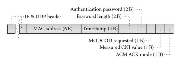
The reception quality report is sent back to the SRMS via the RCS system over UDP/IP using port 3700. The format of the packet containing the report is shown in Figure 4 and is compliant to [9].
Figure 4: UDP packet destined to the SRMS and containing the report.
The MAC address in Figure 4 is used to identify the Probe Receiver sending the report, and the Password field is used to authenticate the message. The value is an 8-bit positive integer value defined as
which means that the reported value can range from 2 dB to 23.5 dB. The ACM ACK Mode field specifies whether an acknowledgement for the proper reception of the report is specified.
The SRMS collects the quality reports from the Probe Receivers, which are periodically sent, and selects the worse one with the minimum value, which corresponds to the Receiver located in the area which experiences the deepest fading. Based on this report, it performs a query on the local lookup table which contains the threshold values and spectral efficiencies of each MODCOD and decides on the MODCOD to be used, robust enough to deliver the video streams with QEF (Quasi Error-Free) requirements at the specified . The decision is sent to the Multiplexer via proprietary signaling over TCP/IP. The Multiplexer, which produces the MPEG-2 Transport Stream to be transmitter, sends to the DVB-S2 ACM Modulator a modified Transport Stream, in which 16 extra bytes have been inserted before each Transport Packet, as shown in Figure 5. These extra bytes contain the MODCOD signaling, which indicates under which transmission scheme this specific Transport Packet is to be transmitted, and are discarded prior to modulation, as they exist solely for the communication between the Multiplexer and the Modulator. The latter conforms to this signaling and transmits each Packet under the designated MODCOD.

Figure 5: Modified Transport Packet sent to the Modulator, containing ACM/MODCOD signaling.
As aforementioned, after each MODCOD change, the subsequent fluctuation in the system capacity must also be compensated, and this is also undertaken by the SRMS. Since the overall symbol rate (in MSymbols/sec) of the DVB-S2 signal is constant, the available overall useful capacity (in Mbps), given the spectral efficiency , of the th MODCOD which is currently being used, is .
According to the relevant priority between the various video streams, each one is assigned a certain constant portion of the available capacity. The approach followed by the SRMS is quite simple, yet fair: each service is assigned, according to its priority, a certain symbol rate, for example, for the th service, with . After every MODCOD change, the bit rate of the service is adjusted in real time to . Since the services contain H.264-encoded programs, the SRMS sends the bit rate change command to the live H.264 encoder, which has been properly modified in order to be able to change the rate of the video stream on the fly, without any interruption and/or visual artifact. The command is organised in an XML structure, which is sent by the SRMS to the encoder over a TCP/IP connection, using the SOAP protocol.
With the aforementioned procedure, the transmission scheme is always robust enough so that the broadcast streams are properly received at any time by all sites. The bit rate of the services is adjusted in real time to match the overall available capacity, which fluctuates as the coding and modulation scheme changes. When reception conditions are good, the TV streams are broadcasted in high bit rate, maintaining good perceptual quality of service (PQoS). When a fading occurs, the rate of the streams lowers, and their PQoS is subsequently degraded. However, they can be still viewed, since the transmitted signal is adequately protected against the fading.
In order to illustrate this concept, we conducted on-air trials, using the configuration of Figure 3, utilising the HellasSat II satellite at 39 degrees East. The core (service provider) platform was located in Toulouse, France, and the receiving node in Athens, Greece. The satellite bouquet contained two H.264 SD services at PAL resolution, whose bit rate could be adapted from 0.5 to 3.0 Mbps. The multiplex was transmitted at a symbol rate of 3 MS/s (rolloff = 0.2, no pilots). A separate DVB-RCS system, supported by a dedicated satellite Gateway, was used for the transport of the reception quality reports from the Probe Receivers back to the SRMS.
Since satellite transmission time was generally limited, and the possibility for a real rain fading to occur within the transmission window was quite small, fading conditions had to be emulated by an external source. For this purpose, an external AWGN source was used, whose output was mixed with the received signal. The impact to the signal was similar with that of a weather fading degradation at the Probe Receiver. An external PC was used to control the output level of the noise source and vary it over time. Figure 6, showing both the noise level and the report, illustrates how at the receiver was affected by the injected noise. The whole level sweep process lasted 10 minutes and the corresponding reports were sent to the SRMS via the DVB-RCS channel.
Figure 6: Variation of Probe Receiver in proportion to injected noise level.
SRMS was configured to react to the incoming reports and modify both video services accordingly. In order to avoid frequent MODCOD changes, not all MODCODs were used, but only these depicted in Table 1. 16APSK and 32APSK were not employed due to hardware limitations.
Table 1: MODCOD combinations used.
Via the procedure described above, MODCOD changes triggered also fluctuations at service rate. Figure 7 shows the variation of the service rates, which were adjusted to conform to the available channel useful capacity. The time (horizontal) axis of the graph is aligned with the one of Figure 6. The service rates were read directly from the log files of the multiplexer, which recorded the bit rate produced by the H.264 encoders. Service 1 has been declared as having higher priority, and that is why it is allocated a higher bit rate than Service 2. In any case, it can be seen that the response of the encoders to bit rate adaptation commands issued by the SRMS is almost immediate (2 seconds response time at maximum).
Figure 7: Adaptation of TV service rates as a result of fluctuation.
The experimental procedure described above proves that the concept of ACM Broadcasting using cross-layer adaptation is technically viable and can be achieved with minor modifications to existing software and hardware modules.
In specific, in order to upgrade a standard DVB-S2 broadcasting system to support ACM, as described, the following required modifications can be summarized:
(i) upgrade of DVB-S2 modulator to support ACM (HW upgrade),
(ii) upgrade of DVB-S2 multiplexer to support ACM (SW upgrade),
(iii) installation of SRMS (SW module),
(iv) upgrade of video encoders to support on-the-fly rate adaptation (SW upgrade),
(v) deployment of Probe Receivers (standard receivers with detection), connected to appropriate terrestrial or satellite return channel (e.g., DVB-RCS),
(vi) installation of ACM Reporting Module into the Probe Receivers (small SW module).
5. Study of Two Full Deployment Scenarios
After the presentation of the proof-of-concept implementation, the next step is to investigate the actual capacity gain derived from a large-scale deployment of a DVB-S2 ACM system for broadcasting services. The comparison will be held against current, static transmission platforms using DVB-S or DVB-S2 CCM.
Since an experimental deployment is not feasible not only due to the significant number of the Probe Receivers which have to be deployed, but mainly due to the extended time period during which the system has to be observed “on-air” in order to derive realistic results, this period should actually be several years. Instead, we conduct a simulation procedure to determine the long-term impact of the employment of ACM in satellite broadcasting. As separate use cases, we consider the provision of broadcast H.264 High Definition TV Services over satellite to two countries: Greece and Indonesia. Both countries include several regions—mostly islands—which are not covered by terrestrial networks, either wired or wireless, and mostly depend on satellite for TV reception.
Ten representative sites in Greece and ten in Indonesia are selected for the installation of the Probe Receivers. These sites are shown in Tables 2 and 3, respectively. Transmission over Ku-band via the transparent transponders of two Ku-band GEO satellites is assumed, HellasSat II at 39° East for Greece and NSS 6 at 95° East for Indonesia.
Table 2: Scenario 1; receiving sites across Greece.
Table 3: Scenario 2; receiving sites across Indonesia.
Since the main factor which could degrade the satellite link is attenuation due to rain [10], by far more important than other effects like scintillation [8] in order to assess the efficiency of the system, we attempt to model the degradation due to rain over time in each of the sites, in both scenarios. For this purpose, we use the empirical statistical model recommended by ITU-R P.618-8 [11]. This model accepts certain parameters such as the location and altitude of the receiving site, the position of the satellite, the downlink frequency and polarisation, and, most important, the rainfall rate for the specific site (in mm/hr) which is exceeded only during 0.01% of the average year, namely, R0.01. The R0.01 parameter is usually available via local weather data and was retrieved by [12] for the Greek sites and by [13] for the Indonesian ones. If local weather data are not available, [14] can provide an R0.01 approximation for all regions in the world.
If a certain “clear sky” is assumed, that is,10 dB in our study, the model can be used to approach the value below which reception is degraded during a given small fraction of the entire year. This is useful when the desired link availability is given as a percentage, and the lowest has to be determined, so that the appropriate MODCOD has to be defined. For the MODCOD selection, the operating thresholds mentioned in [1, 3] for QEF operation have been taken into account, after adding an implementation margin of 2 dB.
For example, in this study, a typical desired link availability of 99.5% is assumed. That is, user satellite receivers should be losing the signal during only 0.5% of the entire year, that is, 43.8 hours of service outage due to rain are allowed. The ITU model produces that, during 99.5% of the year, and assuming that the clear sky is 10 dB, the minimum should be 8.75 dB for Greece (in the site with the deepest fadings) and 6.56 dB for Indonesia, which is a country experiencing frequent and intense rainfalls. That means that, for static transmission, the parameters shown in Table 4 must be used in order to tolerate the aforementioned thresholds.
Table 4: Broadcasting with static transmission in the two scenarios; parameters used and overall capacity for 99.5% required link availability.
The next step is to assess the performance of an ACM-enabled broadcasting system based on DVB-S2, as described in the previous sections. For this purpose, a MATLAB-assisted simulation procedure is followed for each scenario. In each iteration of the simulation, instantaneous values are statistically produced for each site. Then, the behaviour of the SRMS is emulated. The worst report is taken into account, and, based on this, the MODCOD to be used is determined. Video service rates are adapted, and the instantaneous overall useful capacity is recorded. After 106 iterations (corresponding to an actual time period of 2 years), the average capacity is calculated. The results are shown in Table 5. Note that this table shows also the link availability percentage. Since ACM adaptation uses all available MODCODs, service outage really occurs when drops below the threshold of the most robust MODCOD—that is, QPSK 1/4, having a threshold of only 2.35 dB.
Table 5: Broadcasting with DVB-S2 ACM in the two Scenarios—Results.
By comparing Tables 4 and 5, we can derive the actual capacity and availability gain from the use of ACM. In the case of Greece, the increase in capacity is 44.2% compared to DVB-S and 4.6% compared to DVB-S2 CCM, while link outage time drops by 98% to only 31 minutes per year. In the case of Indonesia, the gain is significantly greater; the increase in capacity is 67.3% compared to DVB-S and 29.3% compared to DVB-S2 CCM, while outage time drops by 77.6% to only 9.8 hours per year.
To translate these results to TV broadcasting terms, we can assume that the transmitted multiplex contains H.264 HD television programmes of 6 Mbps on average each. In this case, Figures 8(a) and 8(b) show the number of programs which can be included in an HDTV multiplex within a given transponder bandwidth, using both static and ACM transmission in both scenarios.
Figure 8: (a) Number of HDTV programmes in the multiplex—Greece scenario. (b) Number of HDTV programmes in the multiplex—Indonesia scenario.
It is clear that the application of ACM in HDTV broadcasting in the scenario involving Indonesia leads to a considerable increase in efficiency, allowing for two additional programs in a 36 MHz transponder, compared with DVB-S2 CCM transmission.
The aforementioned simulation included only ten Probe Receivers per case study. It is true that, in an actual deployment, the number of probes needed could be much higher. Thus, there is a risk that a fading report from a single probe, corresponding to a very small portion of the customer base, could force the system to use a more robust MODCOD and thus keep the overall efficiency low. For example, in the Greece case, if we increase the number of probes to 100, the average useful capacity drops to 58.12 Mbps, while a 1000-probe scenario yields an average capacity of just 50.2 Mbps.
In order to compensate this effect, in an actual implementation, it is recommended that each Probe Receiver PRi is assigned a dedicated weight which is proportional to the fraction of the customer base which it represents. A Probe Receiver covering a densely populated city would be assigned a considerably higher weight than one deployed in a small village with just a few customers.
Under this approach, the system administrator could select a specific threshold, namely, , which is equal to the minimum aggregate weight of probe receivers suffering from fading which is needed for a MODCOD change to be decided. Only if the sum of weights of Probe Receivers suffering from fading exceeds , SRMS order is a MODCOD adaptation. Thus, it is ensured that fading reports corresponding to a few customers will not be allowed to affect the overall system capacity. For example, in the aforementioned 1000-probe scenario, just by setting the SRMS to ignore the 5 worst reports from the corresponding probes, the average capacity rises from 50.2 Mbps to 60.1 Mbps. In this sense, the threshold value actually defines the trade-off between efficiency and availability.
The same study can be repeated for any region which is candidate for the use of ACM in broadcasting services. As a general comment, it can be said that the gain from ACM is greater in regions with heavy and frequent rainfalls, since in this case static transmission must employ very robust transmission schemes and is therefore inefficient. Also, naturally, ACM gain is also expected greater in small regions, where reception reports from probe sites are closely correlated. In addition, to further increase efficiency, multispot transmission can be employed, as proposed in [15], following a separate ACM feedback loop for each spot.
6. Conclusions
This article investigated the introduction and application of Adaptive Coding and Modulation in satellite broadcasting services, using the unique feature of the DVB-S2 specification. Instead of using one ACM feedback per user as in unicast services, the deployment of a set of representative Probe Receivers across the service provision area was proposed. A fully functional implemented network showed that the proposed concept is technically viable with minor hardware and software modifications to existing modules of the broadcasting chain. Finally, a theoretical study using realistic scenarios showed capacity gains of up to 67% against DVB-S and 29% against DVB-S2 CCM, respectively.
It must be noted again that efficiency gains from the use of ACM strongly depend on the characteristics of the region in which the broadcast services are provided. Any satellite broadcaster could follow the methodology and rationale presented in this paper in order to determine whether the use of ACM in their specific customer base could lead to a profitable business case.
Established in 2000, the Soukacatv.com main products are modulators both in analog and digital ones, amplifier and combiner. We are the very first one in manufacturing the headend system in China. Our 16 in 1 and 24 in 1 now are the most popular products all over the world.
Source: hindawi