Fundamental to all wireless communications is modulation, the process of impressing the data to be transmitted on the radio carrier. Most wireless transmissions today are digital, and with the limited spectrum available, the type of modulation is more critical than it has ever been.
The main goal of modulation today is to squeeze as much data into the least amount of spectrum possible. That objective, known as spectral efficiency, measures how quickly data can be transmitted in an assigned bandwidth. The unit of measurement is bits per second per Hz (b/s/Hz). Multiple techniques have emerged to achieve and improve spectral efficiency.
HDMI Encoder Modulator,16in1 Digital Headend,HD RF Modulator at SOUKA
https://www.soukacatv.com/.
Amplitude Shift Keying (ASK) and Frequency Shift Keying (FSK)
There are three basic ways to modulate a sine wave radio carrier: modifying the amplitude, frequency, or phase. More sophisticated methods combine two or more of these variations to improve spectral efficiency. These basic modulation forms are still used today withdigital signals.
1. Three basic
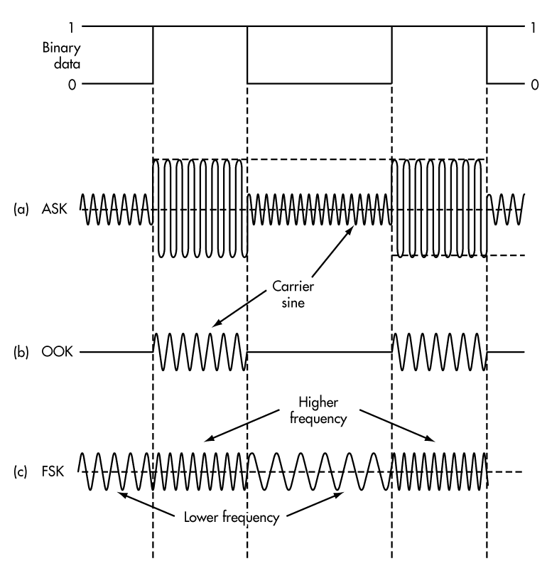
digital modulation formats are still very popular with low-data-rate short-range wireless applications: amplitude shift keying (a), on-off keying (b), and frequency shift keying (c). These waveforms are coherent as the binary state change occurs at carrier zero crossing points.
Figure 1 shows a basic serial digital signal of binary zeros and ones to be transmitted and the corresponding AM and FM signals resulting from modulation. There are two types of AM signals: on-off keying (OOK) and amplitude shift keying (ASK). In Figure 1a, the carrier amplitude is shifted between two amplitude levels to produce ASK. In Figure 1b, the binary signal turns the carrier off and on to create OOK.
AM produces sidebands above and below the carrier equal to the highest frequency content of the modulating signal. The bandwidth required is two times the highest frequency content including any harmonics for binary pulse modulating signals.
Frequency shift keying (FSK) shifts the carrier between two different frequencies called the mark and space frequencies, or fm and fs(Fig. 1c). FM produces multiple sideband frequencies above and below the carrier frequency. The bandwidth produced is a function of the highest modulating frequency including harmonics and the modulation index, which is:
m = Δf(T)
Δf is the frequency deviation or shift between the mark and space frequencies, or:
Δf = fs – fm
T is the bit time interval of the data or the reciprocal of the data rate (1/bit/s).
Smaller values of m produce fewer sidebands. A popular version of FSK called minimum shift keying (MSK) specifies m = 0.5. Smaller values are also used such as m = 0.3.
Here are two ways to further improve the spectral efficiency for both ASK and FSK. First, select data rates, carrier frequencies, and shift frequencies so there are no discontinuities in the sine carrier when changing from one binary state to another. These discontinuities produce glitches that increase the harmonic content and the bandwidth.
The idea is to synchronize the stop and start times of the binary data with when the sine carrier is transitioning in amplitude or frequency at the zero crossing points. This is called continuous phase or coherent operation. Both coherent ASK/OOK and coherent FSK have fewer harmonics and a narrower bandwidth than non-coherent signals.
A second technique is to filter the binary data prior to modulation. This rounds the signal off, lengthening the rise and fall times and reducing the harmonic content. Special Gaussian and raised cosine low pass filters are used for this purpose. GSM cell phones widely use a popular combination, Gaussian filtered MSK (GMSK), which allows a data rate of 270 kbits/s in a 200-kHz channel.
Binary Phase Shift Keying (BPSK) And Quadrature Phase Shift Keying (QPSK)
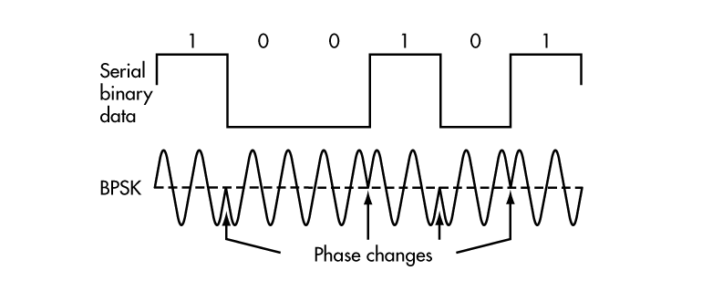
A very popular digital modulation scheme, binary phase shift keying (BPSK), shifts the carrier sine wave 180° for each change in binary state (Fig. 2). BPSK is coherent as the phase transitions occur at the zero crossing points. The proper demodulation of BPSK requires the signal to be compared to a sine carrier of the same phase. This involves carrier recovery and other complex circuitry.
2. In binary phase shift keying, note how a binary 0 is 0° while a binary 1 is 180°. The phase changes when the binary state switches so the signal is coherent.
A simpler version is differential BPSK or DPSK, where the received bit phase is compared to the phase of the previous bit signal. BPSK is very spectrally efficient in that you can transmit at a data rate equal to the bandwidth or 1 bit/Hz.
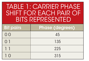
In a popular variation of BPSK, quadrature PSK (QPSK), the modulator produces two sine carriers 90° apart. The binary data modulates each phase, producing four unique sine signals shifted by 45° from one another. The two phases are added together to produce the final signal. Each unique pair of bits generates a carrier with a different phase (Table 1).
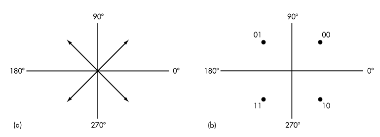
Figure 3a illustrates QPSK with a phasor diagram where the phasor represents the carrier sine amplitude peak and its position indicates the phase. A constellation diagram in Figure 3b shows the same information. QPSK is very spectrally efficient since each carrier phase represents two bits of data. The spectral efficiency is 2 bits/Hz, meaning twice the data rate can be achieved in the same bandwidth as BPSK.
3. Modulation can be represented without time domain waveforms. For example, QPSK can be represented with a phasor diagram (a) or a constellation diagram (b), both of which indicate phase and amplitude magnitudes.
Data Rate And Baud RateThe maximum theoretical data rate or channel capacity (C) in bits/s is a function of the channel bandwidth (B) channel in Hz and the signal-to-noise ratio (SNR):
C = B log2 (1 + SNR)
This is called the Shannon-Hartley law. The maximum data rate is directly proportional to the bandwidth and logarithmically proportional the SNR. Noise greatly diminishes the data rate for a given bit error rate (BER).
Another key factor is the baud rate, or the number of modulation symbols transmitted per second. The term symbol in modulation refers to one specific state of a sine carrier signal. It can be an amplitude, a frequency, a phase, or some combination of them. Basic binary transmission uses one bit per symbol.
In ASK, a binary 0 is one amplitude and a binary 1 is another amplitude. In FSK, a binary 0 is one carrier frequency and a binary 1 is another frequency. BPSK uses a 0° shift for a binary 0 and a 180° shift for a binary 1. In each of these cases there is one bit per symbol.
Data rate in bits/s is calculated as the reciprocal of the bit time (tb):
bits/s = 1/tb
With one symbol per bit, the baud rate is the same as the bit rate. However, if you transmit more bits per symbol, the baud rate is slower than the bit rate by a factor equal to the number of bits per symbol. For example, if 2 bits per symbol are transmitted, the baud rate is the bit rate divided by 2. For instance, with QPSK a 70 Mb/s data stream is transmitted at a baud rate of 35 symbols/second.
Multiple Phase Shift Keying (M-PSK)
QPSK produces two bits per symbol, making it very spectrally efficient. QPSK can be referred to as 4-PSK because there are four amplitude-phase combinations. By using smaller phase shifts, more bits can be transmitted per symbol. Some popular variations are 8-PSK and 16-PSK.
8-PSK uses eight symbols with constant carrier amplitude 45° shifts between them, enabling three bits to be transmitted for each symbol. 16-PSK uses 22.5° shifts of constant amplitude carrier signals. This arrangement results in a transmission of 4 bits per symbol.
While Multiple Phase Shift Keying (M-PSK) is much more spectrally efficient, the greater the number of smaller phase shifts, the more difficult the signal is to demodulate in the presence of noise. The benefit of M-PSK is that the constant carrier amplitude means that more efficient nonlinear power amplification can be used.
Quadrature Amplitude Modulation (QAM)
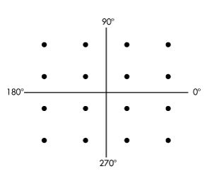
The creation of symbols that are some combination of amplitude and phase can carry the concept of transmitting more bits per symbol further. This method is called quadrature amplitude modulation (QAM). For example, 8QAM uses four carrier phases plus two amplitude levels to transmit 3 bits per symbol. Other popular variations are 16QAM, 64QAM, and 256QAM, which transmit 4, 6, and 8 bits per symbol respectively (Fig. 4).
4. 16QAM uses a mix of amplitudes and phases to achieve 4 bits/Hz. In this example, there are three amplitudes and 12 phase shifts.
While QAM is enormously efficient of spectrum, it is more difficult to demodulate in the presence of noise, which is mostly random amplitude variations. Linear power amplification is also required. QAM is very widely used in cable TV, Wi-Fi wireless local-area networks (LANs), satellites, and cellular telephone systems to produce maximum data rate in limited bandwidths.
Amplitude Phase Shift Keying (APSK)
Amplitude phase shift keying (APSK), a variation of both M-PSK and QAM, was created in response to the need for an improved QAM. Higher levels of QAM such as 16QAM and above have many different amplitude levels as well as phase shifts. These amplitude levels are more susceptible to noise.
Furthermore, these multiple levels require linear power amplifiers (PAs) that are less efficient than nonlinear (e.g., class C). The fewer the number of amplitude levels or the smaller the difference between the amplitude levels, the greater the chance to operate in the nonlinear region of the PA to boost power level.
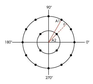
APSK uses fewer amplitude levels. It essentially arranges the symbols into two or more concentric rings with a constant phase offset θ. For example, 16APSK uses a double-ring PSK format (Fig. 5). This is called 4-12 16APSK with four symbols in the center ring and 12 in the outer ring.
5. 16APSK uses two amplitude levels, A1 and A2, plus 16 different phase positions with an offset of θ. This technique is widely used in satellites.
Two close amplitude levels allow the amplifier to operate closer to the nonlinear region, improving efficiency as well as power output. APSK is used primarily in satellites since it is a good fit with the popular traveling wave tube (TWT) PAs.
Orthogonal Frequency Division Multiplexing (OFDM)
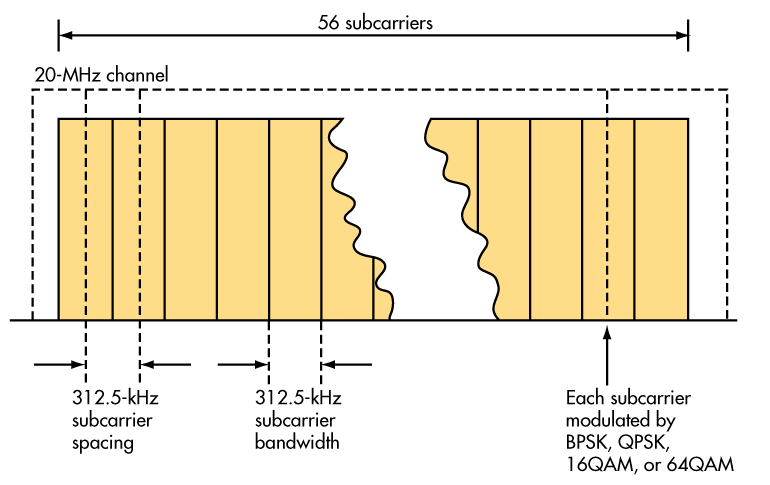
Orthogonal frequency division multiplexing (OFDM) combines modulation and multiplexing techniques to improve spectral efficiency. A transmission channel is divided into many smaller subchannels or subcarriers. The subcarrier frequencies and spacings are chosen so they’re orthogonal to one another. Their spectra won’t interfere with one another, then, so no guard bands are required (Fig. 6).
6. In the OFDM signal for the IEEE 802.11n Wi-Fi standard, 56 subcarriers are spaced 312.5 kHz in a 20-MHz channel. Data rates to 300 Mbits/s can be achieved with 64QAM.
The serial digital data to be transmitted is subdivided into parallel slower data rate channels. These lower data rate signals are then used to modulate each subcarrier. The most common forms of modulation are BPSK, QPSK, and several levels of QAM. BPSK, QPSK, 16QAM, and 64QAM are defined with 802.11n. Data rates up to about 300 Mbits/s are possible with 64QAM.
The complex modulation process is only produced by digital signal processing (DSP) techniques. An inverse fast Fourier transform (IFFT) generates the signal to be transmitted. An FFT process recovers the signal at the receiver.
OFDM is very spectrally efficient. That efficiency level depends on the number of subcarriers and the type of modulation, but it can be as high as 30 bits/s/Hz. Because of the wide bandwidth it usually occupies and the large number of subcarriers, it also is less prone to signal loss due to fading, multipath reflections, and similar effects common in UHF and microwave radio signal propagation.
Currently, OFDM is the most popular form of digital modulation. It is used in Wi-Fi LANs, WiMAX broadband wireless, Long Term Evolution (LTE) 4G cellular systems, digital subscriber line (DSL) systems, and in most power-line communications (PLC) applications. For more, see “Orthogonal Frequency-Division Multiplexing (OFDM): FAQ Tutorial.”
Determining Spectral Efficiency
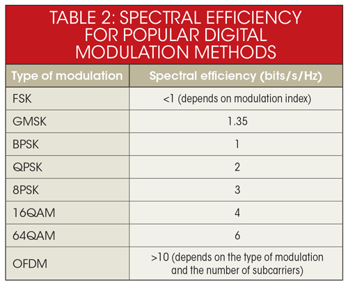
Again, spectral efficiency is a measure of how quickly data can be transmitted in an assigned bandwidth, and the unit of measurement is bits/s/Hz (b/s/Hz). Each type of modulation has a maximum theoretical spectral efficiency measure (Table 2).
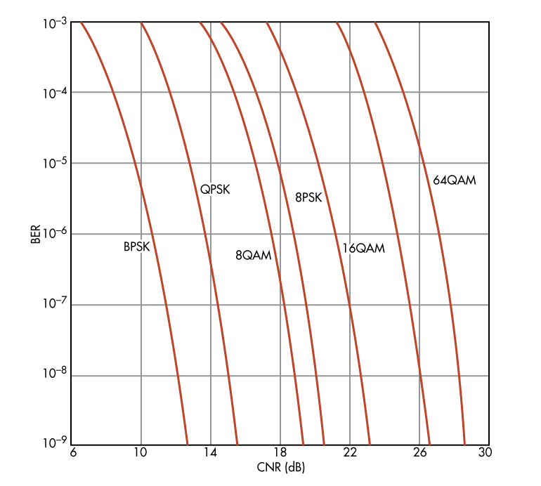
SNR is another important factor that influences spectral efficiency. It also can be expressed as the carrier to noise power ratio (CNR). The measure is the BER for a given CNR value. BER is the percentage of errors that occur in a given number of bits transmitted. As the noise becomes larger compared to the signal level, more errors occur.
Some modulation methods are more immune to noise than others. Amplitude modulation methods like ASK/OOK and QAM are far more susceptible to noise so they have a higher BER for a given modulation. Phase and frequency modulation (BPSK, FSK, etc.) fare better in a noisy environment so they require less signal power for a given noise level (Fig. 7).
7. This is a comparison of several popular modulation methods and their spectral efficiency expressed in terms of BER versus CNR. Note that for a given BER, a greater CNR is needed for the higher QAM levels.
Other Factors Affecting Spectral Efficiency
While modulation plays a key role in the spectral efficiency you can expect, other aspects in wireless design influence it as well. For example, the use of forward error correction (FEC) techniques can greatly improve the BER. Such coding methods add extra bits so errors can be detected and corrected.
These extra coding bits add overhead to the signal, reducing the net bit rate of the data, but that’s usually an acceptable tradeoff for the single-digit dB improvement in CNR. Such coding gain is common to almost all wireless systems today.
Digital compression is another useful technique. The digital data to be sent is subjected to a compression algorithm that greatly reduces the amount of information. This allows digital signals to be reduced in content so they can be transmitted as shorter, slower data streams.
For example, voice signals are compressed for digital cell phones and voice over Internet protocol (VoIP) phones. Music is compressed in MP3 or AAC files for faster transmission and less storage. Video is compressed so high-resolution images can be transmitted faster or in bandwidth-limited systems.
Another factor affecting spectral efficiency is the use of multiple-input multiple-output (MIMO), which is the use of multiple antennas and transceivers to transmit two or more bit streams. A single high-rate stream is divided into two parallel streams and transmitted in the same bandwidth simultaneously.
By coding the streams and their unique path characteristics, the receiver can identify and demodulate each stream and reassemble it into the original stream. MIMO, therefore, improves data rate, noise performance, and spectral efficiency. Newer wireless LAN (WLAN) standards like 802.11n and 802.11ac/ad and cellular standards like LTE and WiMAX use MIMO. For more, see “How MIMO Works.”
Implementing Modulation And Demodulation
In the past, unique circuits implemented modulation and demodulation. Today, most modern radios are software-defined radios (SDR) where functions like modulation and demodulation are handled in software. DSP algorithms do the job previously assigned to modulator and demodulator circuits.
The modulation process begins with the data to be transmitted being fed to a DSP device that generates two digital outputs, which are needed to define the amplitude and phase information required at the receiver to recover the data. The DSP produces two baseband streams that are sent to digital-to-analog converters (DACs) that produce the analog equivalents.
These modulation signals feed the mixers along with the carrier. There is a 90° shift between the carrier signals to the mixers. The resulting quadrature output signals from the mixers are summed to produce the signal to be transmitted. If the carrier signal is at the final transmission frequency, the composite signal is ready to be amplified and sent to the antenna. This is called direct conversion. Alternately, the carrier signal may be at a lower intermediate frequency (IF). The IF signal is upconverted to the final carrier frequency by another mixer before being applied to the transmitter PA.
At the receiver, the signal from the antenna is amplified and downconverted to IF or directly to the original baseband signals. The amplified signal from the antenna is applied to mixers along with the carrier signal. Again, there is a 90° shift between the carrier signals applied to the mixers.
The mixers produce the original baseband analog signals, which are then digitized in a pair of analog-to-digital converters (ADCs) and sent to the DSP circuitry where demodulation algorithms recover the original digital data.
There are three important points to consider. First, the modulation and demodulation processes use two signals in quadrature with one another. The DSP calculations call for two quadrature signals if the phase and amplitude are to be preserved and captured during modulation or demodulation.
Second, the DSP circuitry may be a conventional programmable DSP chip or may be implemented by fixed digital logic implementing the algorithm. Fixed logic circuits are smaller and faster and are preferred for their low latency in the modulation or demodulation process.
Third, the PA in the transmitter needs to be a linear amplifier if the modulation is QPSK or QAM to faithfully reproduce the amplitude and phase information. For ASK, FSK, and BPSK, a more efficient non-linear amplifier may be used.
The Pursuit Of Greater Spectral Efficiency
With spectrum being a finite entity, it is always in short supply. The Federal Communications Commission (FCC) and other government bodies have assigned most of the electromagnetic frequency spectrum over the years, and most of that is actively used.
Shortages now exist in the cellular and land mobile radio sectors, inhibiting the expansion of services such as high data speeds as well as the addition of new subscribers. One approach to the problem is to improve the efficiency of usage by squeezing more users into the same or less spectrum and achieving higher data rates. Improved modulation and access methods can help.
One of the most crowded areas of spectrum is the land mobile radio (LMR) and private mobile radio (PMR) spectrum used by the federal government, state governments, and local public safety agencies like fire and police departments. Currently they’re assigned spectrum by FCC license in the 150- to 174-MHz VHF spectrum and the 421- to 512-MHz UHF spectrum.
Most radio systems and handsets use FM analog modulation that occupies a 25-kHz channel. Recently the FCC has required all such radios to switch over to 12.5-kHz channels. This conversion, known as narrowbanding, doubles the number available channels.
Narrowbanding is expected to improve a radio’s ability to get access to a channel. It also means that more radios can be added to the system. This conversion must take place before January 1, 2013. Otherwise, an agency or business could lose its license or be fined. This switchover will be expensive as new radio systems and handsets are required.
In the future, the FCC is expected to mandate a further change from the 12.5-kHz channels to 6.25-kHz channels, again doubling capacity without increasing the amount of spectrum assigned. No date for that change has been assigned.
The new equipment can use either analog or digital modulation. It is possible to put standard analog FM in a 12.5-kHz channel by adjusting the modulation index and using other bandwidth-narrowing techniques. However, analog FM in a 6.25-kHz channel is unworkable, so a digital technique must be used.
Digital methods digitize the voice signal and use compression techniques to produce a very low-rate serial digital signal that can be modulated into a narrow band. Such digital modulation techniques are expected to meet the narrowbanding goal and provide some additional performance advantages.
New modulation techniques and protocols—including P25, TETRA, DMR, dPMR, and NXDN—have been developed to meet this need. All of these new methods must meet the requirements of the FCC’s Part 90 regulations and/or the regulations of the European Telecommunications Standards Institute (ETSI) standards such as TS-102 490 and TS-102-658 for LMR.
The most popular digital LMR technology, P25, is already in wide use in the U.S. with 12.5-kHz channels. Its frequency division multiple access (FDMA) method divides the assigned spectrum into 6.25-kHz or 12.5-kHz channels.
Phase I of the P25 project uses a four-symbol FSK (4FSK) modulation. Standard FSK, covered earlier, uses two frequencies or “tones” to achieve 1-bit/Hz. However, 4FSK is a variant that uses four frequencies to provide 2-bits/Hz efficiency. With this scheme the standard achieves a 9600-bit/s data rate in a 12.5-KHz channel. With 4FSK, the carrier frequency is shifted by ±1.8 kHz or ±600 Hz to achieve the four symbols.
In Phase 2, a compatible QPSK modulation scheme is used to achieve a similar data rate in a 6.25-kHz channel. The phase is shifted either ±45° or ±135° to get the four symbols. A unique demodulator has been developed to detect either the 4FSK or QPSK signal to recover the digital voice. Only different modulators on the transmit end are needed to make the transition from Phase 1 to Phase 2.
The most widespread digital LMR technology outside of the U.S. is TETRA, or Terrestrial Trunked Radio. This ETSI standard is universally used in Europe as well as in Africa, Asia, and Latin America. Its time division multiple access (TDMA) approach multiplexes four digital voice or data signals into a 25-kHz channel.
A single channel is used to support a digital stream of four time slots for the digital data for each subscriber. This is equivalent to four independent signals in adjacent 6.25-kHz channels. The modulation is π/4-DQPSK, and the data rate is 7.2 kbits/s per time slot.
Another ETSI standard, digital mobile radio (DMR), uses a 4FSK modulation scheme in a 12.5-kHz channel. It can achieve a 6.25-kHz channel equivalent in a 12.5-kHz channel by using two-slot TDMA. The voice is digitally coded with error correction, and the basic rate is 3.6 kbits/s. The data rate in the 12.5-kHz band is 9600 kbits/s.
A similar technology is dPMR, or digital private mobile radio standard. This ETSI standard also uses a 4FSK modulation scheme, but the access is FDMA in 6.25-kHz channels. The voice coding rate is also 3.6 kbits/s with error correction.
LMR manufacturers Icom and Kenwood have developed NXDN, another standard for LMR. It is designed to operate in either 12.5- or 6.25-kHz channels using digital voice compression and a four-symbol FSK system. A channel may be selected to carry voice or data.
The basic data rate is 4800 bits/s. The access method is FDMA. NXDN and dPMR are similar, as they both use 4FSK and FDMA in 6.25-kHz channels. The two methods are not compatible, though, as the data protocols and other features are not the same.
Because all of these digital techniques are similar and operate in standard frequency ranges, Freescale Semiconductor was able to make a single-chip digital radio that includes the RF transceiver plus an ARM9 processor that can be programmed to handle any of the digital standards. The MC13260 system-on-a-chip (SoC) can form the basis of a handset radio for any one if not multiple protocols. For more, see “Chip Makes Two-Way Radio Easy.”
Another example of modulation techniques improving spectral efficiency and increasing data throughput in a given channel is a new technique from NovelSat called NS3 modulation. Satellites are positioned in an orbit around the equator about 22,300 miles from earth. This is called the geostationary orbit, and satellites in it rotate in synchronization with the earth so they appear fixed in place, making them a good signal relay platform from one place to another on earth.
Satellites carry several transponders that pick up the weak uplink signal from earth and retransmit it on a different frequency. These transponders are linear and have a fixed bandwidth, typically 36 MHz. Some of the newer satellites have 72-MHz channel transponders. With a fixed bandwidth, the data rate is somewhat fixed as determined by the modulation scheme and access methods.
The question is how one deals with the need to increase the data rate in a remote satellite as required by the ever increasing demand for more traffic capacity. The answer lies in simply creating and implementing a more spectrally efficient modulation method. That’s what NovelSat did. Its NS3 modulation method increases bandwidth capacity up to 78%.
That level of improvement comes from a revised version of APSK modulation covered earlier. One commonly used satellite transmission standard, DVB-S2, is a single carrier (typically L-band, 950 to 1750 MHz) that can use QPSK, 8PSK, 16APSK, and 32APSK modulation with different forward error correction (FEC) schemes. The most common application is video transmission.
NS3 improves on DVB-S2 by offering 64APSK with multiple amplitude and phase symbols to improve efficiency. Also included is low density parity check (LDPC) coding. This combination provides a maximum data rate of 358 Mbits/s in a 72-MHz transponder. Because the modulation is APSK, the TWT PAs don’t have to be backed off to preserve perfect linearity. As a result, they can operate at a higher power level and achieve the higher data rate with a lower CNR than DVB-S2. NovelSat offers its NS1000 modulator and NS2000 demodulator units to upgrade satellite systems to NS3. In most applications, NS3 provides a data rate boost over DVB-S2 for a given CNR.
Established in 2000, the Soukacatv.com (DSW) main products are modulators both in digital and analog modulators, amplifier and combiner. We are the leading communication supplier in manufacturing the headend system in China. Our 16 in 1 and 24 in 1 now are the most popular products all over the world. For more, please access to
https://www.soukacatv.com/.
Source: electronicdesign