2019年1月10日星期四

Analog and Digital Modulation Basic Introduction

Overview

This tutorial is part of the National Instruments Measurement Fundamentals series. Each tutorial in this series, will teach you a specific topic of common measurement applications, by explaining the theory and giving practical examples. This tutorial covers an introduction to analog and digital modulation.

For the complete list of tutorials, return to the NI Measurement Fundamentals Main page or for more RF tutorials refer to the NI RF Fundamentals Main subpage.

HDMI Encoder Modulator,16in1 Digital Headend, HD RF Modulator at SOUKA https://www.soukacatv.com/.

Table of Contents

1.     Modulation Basics
2.     Digital Modulation
3.     I and Q Data
4.     IQ vs. IF Modulators
5.     Relevant NI Hardware
6.     Conclusions

1. Modulation Basics

Modulation is a process in which a modulator changes some attribute of a higher frequency carrier signal proportional to a lower frequency message signal. If the carrier is represented by the equation

Figure 1. Carrier Signal Equation

a change in the message signal will produce a corresponding change in either the amplitude, frequency, or phase of the carrier. A transmitter can then send this carrier signal through the communication medium more efficiently than the message signal alone. Finally, a receiver will demodulate the signal, recovering the original message.

In Amplitude Modulation (AM), pictured below, the amplitude of the carrier sinusoid changes based on the amplitude of the message.


Figure 2. Amplitude Modulation

The message signal (red) rides on top of the carrier as the amplitudes of both vary with time. The frequency of the carrier, however, is much higher than the frequency of the message. This carrier frequency is the center of the 'channel,' or frequency allocation of this RF signal. Frequency allocations vary depending on the medium of transmission. For broadcast transmissions, where signals are sent through the air, the government regulates frequency allocation. If the RF signal is transmitted over wire, such as in cable television, there is more freedom in the choice of carrier.

In addition to amplitude modulation, frequency modulation varies the frequency of the carrier sinusoid based on the amplitude of the message signal. Similarly, phase modulation changes the phase of the carrier in response to a change in amplitude of the message.

2. Digital Modulation

Digital modulation is similar to analog modulation, but rather than being able to continuously change the amplitude, frequency, or phase of the carrier, there are only discrete values of these attributes that correspond to digital codes. There are several common digital modulation schemes, each varying separate sets of parameters. The simplest type is called On Off Keying (OOK) where the amplitude of the carrier corresponds to one of two digital states. A nonzero amplitude represents a digital one while a zero amplitude is a digital zero. A specific implementation of OOK is Morse Code. Frequency Shift Keying (FSK), seen in Figure 3, is a form of frequency modulation where a certain frequency represents each binary value.

Figure 3. Frequency Shift Keying (FSK)

Finally, Quadrature Amplitude Modulation (QAM) uses combinations of amplitudes and phases to represent more than 2 digital states, as many as 1024.

3. I and Q Data
Before comparing IQ and IF modulators, review the tutorial: "
What is I/Q Data?".

4. IQ vs. IF Modulators


After calculating digital I and Q data from the baseband message signal, there are two methods of converting this data into an analog RF signal. The first method involves converting I and Q data into analog signals, then feeding them into a quadrature encoder. There, they control the amplitudes of two oscillators, operating 90 degrees out of phase. The output of these oscillators is summed, resulting in an RF signal with the appropriate amplitude, phase, and frequency.


Figure 4. IQ Modulation


The next method of converting digital I and Q data to analog RF performs the oscillator scaling and summing in the digital domain. That is, digital sinusoids with a phase difference of 90 degrees are scaled by the digital I and Q values, then added together. These digital sinusoids are of a lower frequency than the analog oscillators in the IQ modulation scheme, but still at a significantly higher frequency than the message signal. A digital to analog converter (DAC), which operates at a much higher frequency than the DAC used in IQ modulation, converts the resulting digital waveform to low frequency analog RF. Finally, an analog IF to RF upconverter uses several stages of mixing and filtering to shift the analog RF signal to the desired RF frequency.


Figure 5. IF Modulation

·         The NI 5660 RF Vectors Signal Analyzer and the NI 5671 RF Vector Signal Generator use the IF modulation scheme depicted in Figure 5.

5. Relevant NI Hardware
Customers interested in this topic were also interested in the following NI products:

·         NI RF & Communications Platform
·         NI 5660 2.7 GHz RF Vector Signal Analyzer
·         NI 5671 2.7 GHz RF Vector Signal Generator
·         NI RF Switch Hardware
·         NI Modulation Toolkit Software

6. Conclusions

This document is meant to provide a brief introduction to analog and digital modulation.

For the complete list of tutorials, return to the NI Measurement Fundamentals Main page or for more RF tutorials refer to the NI RF Fundamentals Main subpage.

Established in 2000, the Soukacatv.com (DSW) main products are modulators both in digital and analog modulators, amplifier and combiner. We are the leading communication supplier in manufacturing the headend system in China. Our 16 in 1 and 24 in 1 now are the most popular products all over the world. For more, please access to https://www.soukacatv.com.


Source: http://www.ni.com/white-paper/3013/en/

2019年1月9日星期三

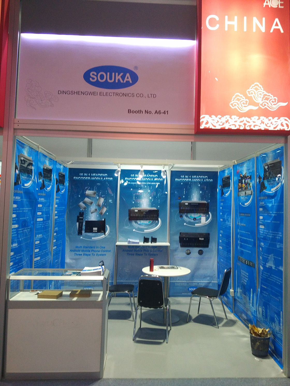
SOUKA at CABSAT 2017 | Soukacatv.com

SOUKA's ALL-IN-ALL-OUT headend with 16 HDMI input and 1 RF output, provides an intuitive interface that is both fast to learn and quick to work with. It only takes three steps and you will have a 16-HD-channel system.
The 16 in 1 digital headend--SK-16D is like a small system, which is able to transmit the HDMI signal into any system standard (ATSC/DVB-C/DVB-T/DTMB/ISDB) connected to the network. The applications include universities, school, hospital, bar and conference rooms. You don't need to know that much on how to setting up the whole system, for we have integrate the encoder and QAM modulator in that small box and set it perfectly to most of the situations.
HDMI Encoder Modulator,16in1 Digital Headend, HD RF Modulator at SOUKA https://www.soukacatv.com/.
For those who want more professional settings, we also offer two kinds of control management : Mobile phone and computer software. Please find the links below:
The SOUKA 16 in 1 encoder modulator headend with its compact design and competitive price has set fire to the market. However, in the coming day we will improve it from 16 HDMI input to 32 HDMI input with the same chassis.
(DSW) is dedicated to design, manufacture and sales of CATV analog & digital headend with our brand name SOUKA. DSW obtained ISO9001:2008 certificate authorized by CQC. We have 100 in-house skillful workers, which ensures the punctual delivery date. And a professional engineer team made up of 10 senior RF engineers and 6 IT engineers to fulfil precise management over all projects honored by our customers.
As one of the most reliable suppliers in this field, we continually spare no efforts in developing DSW into a world recognized brand with trustworthy and solid reputation. DSW sincerely invites you to enjoy the fascinating experience of modern technology and excellent customer service provided for you by our professional staff.
Our main products are modulators both in analog and digital ones, amplifier and combiner. We are the very first one in manufacturing the headend system in China. Our 16 in 1 and 24 in 1 now are the most popular products all over the world.
In 2016,we launched the digital 16 in 1 headend with 1080P output,which supports all digital TV standards in the world. And we never stop our steps,more products will be released in the coming days. We are young but we have faith to find our path to the peak.
20170413225817_54856 (1)
20170413225843_98499

Source: https://www.soukacatv.com/souka-at-cabsat-2017_n11

2019年1月8日星期二

Introduction to Modulation Transfer Function | Soukacatv.com

When optical designers attempt to compare the performance of optical systems, a commonly used measure is the modulation(can be divided into digital and analog modualtors according to the different functions) transfer function (MTF). MTF is used for components as simple as a spherical singlet lens to those as complex as a multi-element telecentric imaging lens assembly. In order to understand the significance of MTF, consider some general principles and practical examples for defining MTF including its components, importance, and characterization.
HDMI Encoder Modulator,16in1 Digital Headend,HD RF Modulator at SOUKA https://www.soukacatv.com/.

THE COMPONENTS OF MTF

To properly define the modulation transfer function, it is necessary to first define two terms required to truly characterize image performance: resolution and contrast.

Resolution

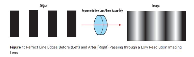
Resolution is an imaging system's ability to distinguish object detail. It is often expressed in terms of line-pairs per millimeter (where a line-pair is a sequence of one black line and one white line). This measure of line-pairs per millimeter (lp/mm) is also known as frequency. The inverse of the frequency yields the spacing in millimeters between two resolved lines. Bar targets with a series of equally spaced, alternating white and black bars (i.e. a 1951 USAF target or a Ronchi ruling) are ideal for testing system performance. For a more detailed explanation of test targets, view Choosing the Correct Test Target. For all imaging optics, when imaging such a pattern, perfect line edges become blurred to a degree (Figure 1). High-resolution images are those which exhibit a large amount of detail as a result of minimal blurring. Conversely, low-resolution images lack fine detail.
1
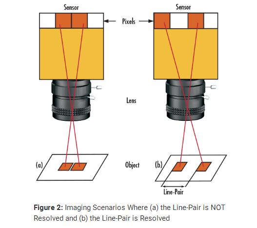
A practical way of understanding line-pairs is to think of them as pixels on a camera sensor, where a single line-pair corresponds to two pixels (Figure 2). Two camera sensor pixels are needed for each line-pair of resolution: one pixel is dedicated to the red line and the other to the blank space between pixels. Using the aforementioned metaphor, image resolution of the camera can now be specified as equal to twice its pixel size.
2.jpg
Correspondingly, object resolution is calculated using the camera resolution and the primary magnification (PMAG) of the imaging lens (Equations 1 – 2). It is important to note that these equations assume the imaging lens contributes no resolution loss.
3

Contrast/Modulation

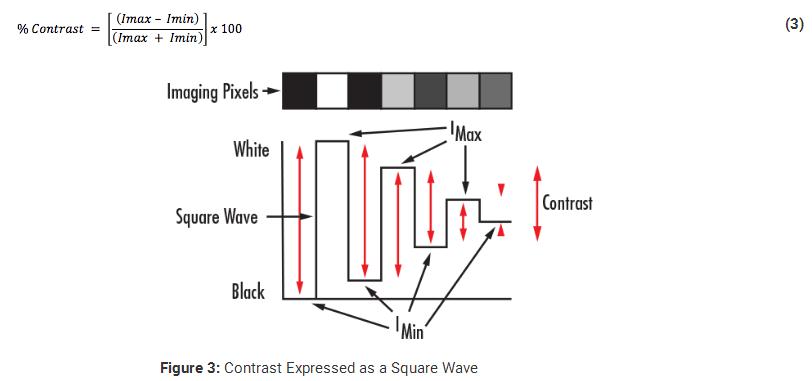
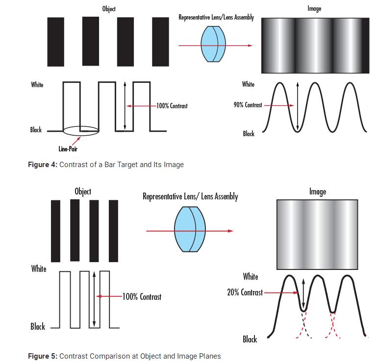
Consider normalizing the intensity of a bar target by assigning a maximum value to the white bars and zero value to the black bars. Plotting these values results in a square wave, from which the notion of contrast can be more easily seen (Figure 3). Mathematically, contrast is calculated with Equation 3:
4
When this same principle is applied to the imaging example in Figure 1, the intensity pattern before and after imaging can be seen (Figure 4). Contrast or modulation can then be defined as how faithfully the minimum and maximum intensity values are transferred from object plane to image plane.

To understand the relation between contrast and image quality, consider an imaging lens with the same resolution as the one in Figure 1 and Figure 4, but used to image an object with a greater line-pair frequency. Figure 5 illustrates that as the spatial frequency of the lines increases, the contrast of the image decreases. This effect is always present when working with imaging lenses of the same resolution. For the image to appear defined, black must be truly black and white truly white, with a minimal amount of grayscale between.
5.jpg

In imaging applications, the imaging lens, camera sensor, and illumination play key roles in determining the resulting image contrast. The lens contrast is typically defined in terms of the percentage of the object contrast that is reproduced. The sensor's ability to reproduce contrast is usually specified in terms of decibels (dB) in analog cameras and bits in digital cameras.

Established in 2000, the Soukacatv.com (DSW) main products are modulators both in digital and analog modulators, amplifier and combiner. We are the leading communication supplier in manufacturing the headend system in China. Our 16 in 1 and 24 in 1 now are the most popular products all over the world. For more, please access to https://www.soukacatv.com/.


Source: edmundoptics

2019年1月3日星期四

Why do we need modulation? | Soukacatv.com

Modulation
Modulation is an important step of communication system. Modulation is defined as the process whereby some characteristic (line amplitude, frequency, phase of a high frequency signal wave (carrier wave) is varied in accordance with instantaneous value intensity of low frequency signal wave (modulating wave.)
HDMI Encoder Modulator,16in1 Digital Headend, HD RF Modulator at SOUKA https://www.soukacatv.com/.
Need for modulation : 
i) To separate signal from different transmitters :
Audio frequencies are within the range of 20 Hz to 20 kHz. Without modulation all signals at same frequencies from different transmitters would be mixed up. There by giving impossible situation to tune to any one of them. In order to separate the various signals, radio stations must broadcast at different frequencies.
Each radio station must be given its own frequency band. This is achieved by frequency translation as a result of modulation process.
ii) Size of the antenna :
For efficient transmission the transmitting antennas should have length at least equal to a quarter of the wavelength of the signal to be transmitted. For an electromagnetic wave of frequency 15 kHz, the wavelength λ is 20 km and one-quarter of this will be equal to 5 km. Obviously, a vertical antenna of this size is impractible. On the other hand, for a frequency of 1 MHz, this height is reduced to 75 m.
Also, the power radiated by an antenna of length l is proportional to (l/λ). This shows that for the same antenna length, power radiated is large for shorter wavelength. Thus, our signal which is of low frequency must be translated to the high frequency spectrum of the electromagnetic wave. This is achieved by the process of modulation.
iii)To Reduce  Antenna Height.(practicability of antennas height).
iv)Transmit The Information To long Distance Without  interference.
v) Reduce band width.
Other answers have described modulation as it applies to communications applications, where the information to be conveyed is superimposed onto a carrier. My answer will apply the concept of modulation to power electronics applications, particularly in DC-AC inverters.
Refer to Figure 1. This shows a typical 3-phase inverter bridge. Six electronic switches are arranged in three-phase bridge configuration, and are supplied by a DC voltage source. These switches are high-power electronic devices. The devices are shown as transistors, but can be SCRs, GTOs, Darlington transistors, MOSFETs or IGBTs. The most suitable devices will be governed by conversion power, voltage level and switching frequencies requirements. The load is shown as an induction motor, but may be the primary of a three-phase transformer or any other A.C. load.
Figure 1: Three-phase Inverter Switches and Waveforms
If each of the three phases are switched in this manner, but with the switching of each phase 120 electrical degrees delayed from the previous phase, the three waveforms of the centre points (VAO, VBO, VCO) are as shown in the figure. If the difference in voltage between any two phases is measured, (VAB in the figure), the result is a 6-step or quasi-square wave. VBC and VCA are the same except are phase shifted 120 degrees from each other.
Thus the output of the three-phase inverter bridge is a three-phase waveform. The frequency of the waveform is set by the switching frequency. The RMS voltage is controlled by modulating the waveform. In practice, the waveform is pulse width modulated with chops.. These chops are of varying size. The purpose is twofold: to make the inverter output currents more closely resemble a sine wave, and to enable adjustment of the RMS output voltage.
Figure 2: Sinusoidal Modulation of Inverter Output Waveform
A method of modulation often used is sinusoidal modulation. . Refer to Figure 2. A triangle waveform is compared with a sine waveform. When the sine wave exceeds the triangle wave, the top switch of the inverter phase is turned on. When the triangle wave exceeds the sine wave, the bottom switch is turned on. The resultant current waveform to the load is nearly sinusoidal with very little harmonic distortion. If the load is an induction motor, no further filtering is required.
If the inverter is fixed frequency, such as in a UPS, then further filtering is needed. The harmonic distortion content is a function of the modulation frequency of the carrier wave. At a high modulation frequency, the first significant harmonic will be at high frequency and low magnitude, which means that harmonics are relatively easy to filter out with a low-pass LC filter. Typical modulation frequency with IGBT power switches is 4kHz.
In the process of modulation, the baseband signal is translated i.e., shifted from low frequency to high frequency . This frequency shift is proportional to the frequency of carrier.
Advantages of Modulation
1. Reduction in the height of antenna
2. Avoids mixing of signals
3. Increases the range of communication
4. Multiplexing is possible
5. Improves quality of reception
We will discuss each of these advantages in detail below .
1. Reduction in the height of antenna
For the transmission of radio signals, the antenna height must be multiple of λ/4 ,where λ is the wavelength .
λ = c /f
where c : is the velocity of light
f: is the frequency of the signal to be transmitted
The minimum antenna height required to transmit a baseband signal of f = 10 kHz is calculated as follows :
The antenna of this height is practically impossible to install .
Now, let us consider a modulated signal at f = 1 MHz . The minimum antenna height is given by,
This antenna can be easily installed practically . Thus, modulation reduces the height of the antenna .
2. Avoids mixing of signals
If the baseband sound signals are transmitted without using the modulation by more than one transmitter, then all the signals will be in the same frequency range i.e. 0 to 20 kHz . Therefore, all the signals get mixed together and a receiver can not separate them from each other .
Hence, if each baseband sound signal is used to modulate a different carrier then they will occupy different slots in the frequency domain (different channels). Thus, modulation avoids mixing of signals .
3. Increase the Range of Communication
The frequency of baseband signal is low, and the low frequency signals can not travel long distance when they are transmitted . They get heavily attenuated .
The attenuation reduces with increase in frequency of the transmitted signal, and they travel longer distance .
The modulation process increases the frequency of the signal to be transmitted . Therefore, it increases the range of communication.
4. Multiplexing is possible
Multiplexing is a process in which two or more signals can be transmitted over the same communication channel simultaneously .
This is possible only with modulation.
The multiplexing allows the same channel to be used by many signals . Hence, many TV channels can use the same frequency range, without getting mixed with each other or different frequency signals can be transmitted at the same time .
5. Improves Quality of Reception
With frequency modulation (FM) and the digital communication techniques such as PCM, the effect of noise is reduced to a great extent . This improves quality of reception .
We need to modulate signal for following reason basically :
1: Transmission of signal to longer distance : For transmitting a signal to the longer distance you need to have maximum amplitude and frequency which is impossible to acquire from original signal.
2: Multiplexing the signal: Modulating signals on different frequencies give us the option to mix and send multiple signals through a single channel and separate out easily.
3: Reduction in Antenna height: Well, Antenna theory will be helpful for understanding this. Simply I remembered that height H of antenna is proportional to the wavelength (Lamda) of the signal.
4: Noise immunity: Modulated signals are high frequency high amplitude signals and hence noise is not so easily affecting the information as every modulation technique using different phenomena to store data.
5: Noise availability: Modulated signals consist frequencies and amplitudes decided by the designer and so according to the channel noise and interference we can decide parameters and avoid noise.
6: Ease of transmission and reception: As we know baseband i.e. original signals can't be transmitted directly as they are not supported by most of channels and also fade away after particular distance, so we need modulation.
This one's easy. I'll give you two instances why modulation is needed.
INSTANCE 1:
Consider you're on a bank of one side of a river and I'll give you a paper and tell you to throw it to the other side of the bank! Is it possible to throw the paper which doesn't have suitable mass to other side of the river?
The answer is No. So in order to make the paper reach the other side of the river I'll use a stone with the paper and throw it, now it'll reach the other side.
In communication the message signal will be of low frequency which is like paper (light weight) in order to make it heavy, a carrier signal(stone) is used to send data from transmitting station to the receiving station.
INSTANCE 2:
Consider you have food and you have to take it to school for lunch, will you carry the food with your hand? No right? You'll use a carrier box and you'll eat the food not the carrier box.
In communication food(message signal) cannot be transmitted as it is, it needs a carrier box(carrier signal)to which is used to enclose the message signal from the transmitter end and carry the modulated signal through the medium and at the receiver the carrier box(carrier signal) is removed by demodulation it removes the envelope and obtains the food(message signal).
This is why modulation and demodulation is required in communication systems.
Dictionary definition: changing any one of the parameters of carrier signal such as amplitude, frequency or phase of the signal with respect to the input voltage of the message signal at that particular instance of time and keeping the other parameters constant is called as modulation.
Few other reasons why modulation is required is as follows.
1) TO REDUCE THE HEIGHT OF THE ANTENNA
2) TO MULTIPLEX MORE NUMBER OF SIGNALS
3) TO REDUCE THE NOISE & DISTORTIONS
4) TO NARROW BANDING THE SIGNAL
5) TO REDUCE EQUIPMENT COMPLEXITY
Very simply because of physics. Let's say you want to communicate from one person to another using just a really really long wire (cable communications). The way that you model a long wire is using a infinite number of capacitors and inductors, as shown below:
For simplicity, you can say that both connections have a shared ground, so all the bottom inductors don't participate, and all the capacitors connect to ground on the bottom. If we say all the capacitances are the same and all inductances are the same (again an approximation that the wire is homogeneous), and you sum these infinitely, you will get a DC resistance. What this means it that this lossless long wire (meaning it has no resistors in it), will transmit nothing at DC, because all of the voltage will drop across the resistor.
Thus the only way to transfer anything across a long wire is through AC (alternating current). Thus you need high frequency modulation in order to communicate.
In the modulation process, two signals are used namely the modulating signal and the carrier .
The modulating signal is nothing but the baseband signal or information signal while the carrier is a high frequency sinusoidal signal .
In the modulation process, some parameter of the carrier wave (such as amplitude, frequency or phase ) is varied in accordance with the modulating signal . This modulated signal is then transmitted by the transmitter .
The receiver demodulates the received modulated signal and gets the original information signal back .
Thus, demodulation is exactly opposite to modulation .
In the process of modulation the carrier wave actually acts as carrier which carries the information signal from the transmitter to receiver .
Need of Modulation
You may ask, when the baseband signal can be transmitted directly why to use the modulation ?
The answer is that the baseband transmission has many limitations which can be overcome using modulation . It is explained below .
In the process of modulation, the baseband signal is translated i.e., shifted from low frequency to high frequency . This frequency shift is proportional to the frequency of carrier.
Advantages of Modulation
1. Reduction in the height of antenna
2. Avoids mixing of signals
3. Increases the range of communication
4. Multiplexing is possible
5. Improves quality of reception
Modulation is a process in which the feature (amplitude, phase or frequency ) of the carrier signal is changed in accordance with instantaneous value of modulating signal.
Modulation is needed for many reasons. Some of them are given below :
To increase the bandwidth of the signals
To reduce the antenna size.
To reduce the noise and distortions.
To multiplex the signals
To reduce the interference at the time of transmission of the information.
In a carrier communication system, the baseband signal of a low-frequency spectrum is translated to a high frequency spectrum. This is achieved through modulation. The aim of this topic is to explore the reasons for using modulation. Modulation is defined as a process by virtue of which, some characteristic of a high frequency sinusoidal wave is varied in accordance with the instantaneous amplitude of the baseband signal.
Two signals are involved in the modulation process. The baseband signal and the carrier signal. The baseband signal is to be transmitted to the receiver. The frequency of this signal is generally low. In the modulation process, this baseband signal is called the
modulating signal. The waveform of this signal is unpredictable. For example, the waveform of a speech signal is random in nature and cannot be predicted. In this case, the speech signal is the modulating signal.
The other signal involved with the modulation is a high frequency sinusoidal wave. This signal is called the carrier signal or carrier.
The frequency of the carrier signal is always much higher than that of the baseband signal. After modulation, the baseband signal of low frequency is transferred to the high frequency carrier, which carries the information in the form of some variations. After the completion of the modulation process, some characteristic of the carrier is varied such that the resultant variations carry the information.
The carrier signal is represented by the equation:
A=E sin(ωt + ϕ)——(1)
equation-(1) is an indicator that this equation represents the carrier signal. The components of this equation arc as follows:
A: Instantaneous amplitude of the carrier
E: Amplitude of the carrier
ϕ: Initial phase of the carrier signal
Angular frequency of the carrier, such that = 2πfc, Where fc is the frequency carrier, also called the central frequency
Equation (1) has three parameters namely, amplitudes (E), frequency (ω), and phase (f). In principle, these parameters have constant values for a particular sinusoidal wave. According to the definition of Modulation, some characteristic of the carrier signal is varied in accordance with the modulating signal. After modulation any one of the three parameters of the carrier signal, namely, frequency, or phase, is varied keeping the remaining two constant.
The baseband signal is then carried by these variations. The type of the modulation is decided by the parameter chosen to vary.
For example, if amplitude of the carrier is chosen to vary in accordance with the instantaneous amplitude of the baseband signal, keeping frequency and phase constant, the resulting modulation called amplitude modulation. Frequency modulation and phase modulation are also obtained in a similar way.
Low-frequency baseband sign it is thus translated to a high frequency carrier such that the information is coded in the variations in one of the parameters of the carrier. At the receiver side, these variations are detected through the demodulation process to recover the original baseband signal.
The following can be summarized with reference to modulation.
The baseband signal is known as the modulating signal.
The baseband signal is a low-frequency signal.
The carrier signal is always a high frequency sinusoidal wave.
After modulation, the carrier is said to be modulated by the modulating.
The output of the modulator is called the modulated signal.
During the modulation process, the modulating, signal varies the frequency, y, amplitude, or phase of the carrier in accordance with its instantaneous amplitude.
The process of modulation in a communication system increases its cost and complexity. This may be considered as a disadvantage. However, modulation is extensively used in most communication systems. There is a definite need for using modulation. There can be problems if modulation is not used. Scrutinizing these problems can explain why modulation is required.
The baseband signal will be transmitted as it is. If modulation is not employed however, the system designer could confront the fallowing problems:
1) TO REDUCE THE ANTENNA HEIGHT
2) TO MULTIPLEX THE MORE NUMBER OF SIGNALS
3) TO REDUCE THE NOISE & DISTORTIONS
4) TO NARROW BANDING THE SIGNAL
5) TO REDUCE EQUIPMENT COMPLEXITY
Established in 2000, the Soukacatv.com (DSW) main products are modulators both in digital and analog modulators, amplifier and combiner. We are the leading communication supplier in manufacturing the headend system in China. Our 16 in 1 and 24 in 1 now are the most popular products all over the world. For more, please access to https://www.soukacatv.com/.

Source: https://www.quora.com/Why-do-we-need-modulation

2019年1月2日星期三

Delivering Data Via Digital Modulation | Soukacatv.com

Digital modulation in many forms has proven to be an effective means of delivering voice, data, and video through the limited channel bandwidths of modern wireless communications networks.

HDMI Encoder Modulator,16in1 Digital Headend, HD RF Modulator at SOUKA
Simply put, digital modulation has made the modern wireless communications revolution possible. As users of wireless communications devices seek greater capacity to send and receive voice-, data- and video-laden signals, network operators have come to rely on communications standards based on high-capacity digital modulation formats.
Modulation of any form relies on controlled changes in one or more of a periodic waveform's three basic parameters: amplitude, frequency, and phase. By changing or modulating a carrier signal in one or more of these parameters, information can be added or modulated to the carrier at the transmit end of a system, then recovered or demodulated at the receive end of the system. Traditional analog forms of modulation relied on simple changes to amplitude, frequency, or phase. But bandwidth is limited, and modern communications systems are required to transport increasing amounts of information over channels with relatively narrow bandwidths. Just like their analog counterparts, digital modulation formats manipulate the three basic carrier signal parameters, but do so in discrete states representing digital bits. Basic forms of digital modulation include amplitude shift keying (ASK), frequency shift keying (FSK), phase shift keying (PSK), and modulation in which several of the parameters are combinedsuch as quadrature amplitude modulation (QAM), in which at least two discrete phase states and amplitude states are used to transfer information.
Digitally modulated signals are typically generated through use of in-phase (I) and quadrature (Q) rectangular signal coordinates, which can be added to a carrier via a pair of frequency mixers, one of which is 90 deg. offset from the other. Binary phase shift keying (BPSK) is a simple form of digital modulation, keeping amplitude constant but shifting the phase between 0 and 180 deg. In quadrature phase shift keying (QPSK), four phase states are used.
Digital modulation formats are characterized in terms of their symbol rates, or the number of bits that are transmitted per modulation state. In BPSK, for example, one bit per symbol is transmitted. Because the modulation is either at 0 or 180 deg., there is one I signal state and one Q signal state. In QpSK, in which two I and two Q values are transmitted, the modulation format sends two bits per symbol. As a result, QPSK is potentially twice as bandwidth efficient as BPSK. As modulation formats increase in complexity, they can send an increasing amount of data over a given portion of the RF/microwave spectrum. Additional variants of pSK include eight-state PSK (8PSK), 16-state PSK (16PSK), differential PSK (DPSK), differential quadrature PSK (DQPSK), offset quadrature pSK (OQPSK), and p-4 quadrature PSK (p-4-QPSK).
For example, in 16QPSK, there are four I signal states and four Q signal states, so that a total of 4 x 4 or 16 signal states can be transmitted. In this modulation format, four bits per symbol are transmitted; that is, the symbol rate is one quarter the bit rate, making 16QPSK more spectrally efficient than a less complex form of this modulation format (such as simple QPSK, with two bits per symbol).
Varying signals with time, or multiplexing, is also often used with digital modulation formats to achieve efficient use of available frequency spectrum. Typical multiplexing formats include frequency-division multiple access (FDMA), time-division multiple access (TDMA), and code-division multiple access (CDMA).
 The symbol rate, also known as the baud rate, determines the amount of bandwidth required by a carrier of a given modulation format. The symbol rate is equal to the bit rate divided by the number of bits transmitted per symbol. For example, a system with bit resolution of 8 b operating at a sampling rate of 1 MHz produces a bit stream of 8 b x 1 mHz = 8 MHz.
With more complex forms of digital modulation come greater linearity and noise requirements in a system, as an increased number of bits and symbols are packed closer together. Sometimes increased transmission power might be needed to keep the symbols of a complex modulation format properly spaced for demodulation.
Established in 2000, the Soukacatv.com (DSW) main products are modulators both in digital and analog modulators, amplifier and combiner. We are the leading communication supplier in manufacturing the headend system in China. Our 16 in 1 and 24 in 1 now are the most popular products all over the world. For more, please access to https://www.soukacatv.com/.


Sourcehttps://www.mwrf.com/content/delivering-data-digital-modulation

2019年1月1日星期二

What is the difference between digital signal and analog signal? | Soukacatv.com

Differences between analog signal and digital signal are given below :
·         Analog signal is a continuous signal whereas Digital signal is discrete time signal.
·         Analog signal is denoted by sin waves whereas Digital signal is denoted by square waves.
·         Analog signal has high noise whereas Digital signal has less noise.
·         Analog signal is stored in the form of wave signal whereas Digital signal is stored in the form of binary bit.
·         Analog signal has less cost whereas Digital signal has high cost.
·         Analog signal example is - Human voice whereas Digital signal example is Computer system.

HDMI Encoder Modulator,16in1 Digital Headend,HD RF Modulator at SOUKA https://www.soukacatv.com/.

Purely digital signals exist as a sequence of samples. These samples might be stored somewhere or digitally processed. They are both discrete in time and quantized in amplitude.
Analog signals are the physical signals that propagate through some medium i.e. a circuit, cable, the air, etc. They are continuous in both time and amplitude.
The reason I started by talking about “purely” digital signals is because that’s really an abstraction. The reality is that everything in this world is analog. When we talk about a digital circuit which reads/writes a byte of data, the reality is that the circuit operates on analog inputs and outputs. But by intelligently designing the circuit we can abstract away these details and just think about the digital signals. A wireless transmission that contains digital information still ultimately uses an analog signal to propagate through the air.
Analog signal: (continues signals )
1.analog signal is continues signals which represents physical measurements .
2.wave : denoted by sine wave
3. Example : Human voice in air, analog electronic devices.
4.Representation:Uses continuous range of values to represent information
5.Data transmissions :Subjected to deterioration by noise during transmission and write/read cycle.
6. Uses : Can be used in analog devices only. Best suited for audio and video transmission.
Digital Signals
1.Digital signals are discrete time signals generated by digital modulation.
2.wave : denoted by square wave
3.Examples :Computers, CDs, DVDs, and other digital electronic devices.
4. Representation: Uses discrete or discontinuous values to represent information
5.Data Transmission: Can be noise-immune without deterioration during transmission and write/read cycle.
6.Uses :Best suited for Computing and digital electronic.
The following graph is more clear in understanding there signals..

Main difference you get between analog and digital signals is that analog real time Signals and digital signals that are performed within the system it's basically your voice my voice and everyone else's voice is analogue because suppose you are speaking a sentence you are going to spell it till the end Undertaker instead of time I can measure a certain DB of noise coming from your mouth so this noise is introduced into the transducer which converts it into voltage signals now the signals are analog in nature the main thing which we get defect is analogue parts has many losses and also the computational time is pretty high compared to the digital so we use an analogto digital converter to convert these analog signals into digital signals by the help of sampling that is we take the values of the signal at every small instant of time this small instant of time is very small and it has to follow nyquist criterion I am not going into the details of this criterion about it in the later stages but the sampling is basically we are taking the values of this signal at every small instant of time such that will get a large value of the data of the original signal. These data are converted into zeros and ones and processes in the system which are digital in nature and finally after all the computations it is converted do analog

To understand this difference, let us go back a bit and start with the very basics:
Q: What is a signal?
- A signal is a plot of the value of a physical quantity/parameter with respect to time. In other words, a signal carries information about the change in the value of a quantity/parameter over a period of time. The physical quantity could be anything that we are trying to measure, like temperature, speech, light intensity etc.
NOTE- If the physical quantity being measured is an electrical parameter, like Voltage or Current, then the signal is called an electrical signal.

- An analog signal is continuous with respect to time; meaning its value changes continuously with time. In other words, an analog signal will have a value at any given instant of time. For example, the value of an analog signal can be extracted at 0s, 1.5s, 4.908675s etc.
- All real world signals are analog in nature.
Q: What are signals used for?
- There are three things that can be done with a signal:
1.Store the signal for later use
2.Process the signal (convert it to some other form, perform some operations on the signal etc)
3.Transmit the signal to some other destination to be used there.
- Now, since analog signals are continuous, it will have infinite number of values considering the value at each instant of time. Therefore, storing such a signal requires large amount of memory; processing requires large processing power or more time; transmitting requires a large bandwidth.
Q: So, is there an easy way to handle signals?
- YES. Instead of measuring/considering the signal value at every instant of time, lets take the signal value only at desired instances of time. In other words, we consider signal "samples" at specific instances of time.

- Above picture shows an analog signal sampled at specific time instances (t1 - t10). Such a signal is called as a "discrete time signal", since the signal values are represented at discrete time units. In technical terms, the signal values are called as "samples" and this process is called as "sampling". Closer these samples are, more accurate will be the signal representation. The number of samples to be considered is determined by the "sampling rate" of the system.
- With discrete time signal, there's a problem. The amplitude of the samples can be real numbers (5.38239, 13.57236 etc) representing which may become tedious. To overcome this, just like we divided the x-axis at discrete intervals, let us also divide the y-axis at discrete intervals.

- If the signal amplitude falls between 0 and L1, let us round it off to 0. If the signal amplitude falls between L1 and L2, we round it off to L1 and so on. Again, the closer these levels are, more accurate will be the signal representation.
- This process is called as "quantization" and the resulting quantized signal is called a "Digital Signal".
- Most digital systems today make use of only two signal levels, Level0 and Level1.
- These signal levels have different names in the world of digital electronics;
Level0 or Logic0/OFF/False/Absent
Level1 or Logic1/ON/True/Present
- That is, at any given instant of time the signal is either present or it is absent. If it is present, we call it Logic1, or simply 1, and if it is absent we call it Logic0, or simply 0.
- Analog signals are converted into digital signals, processed in digital form and converted back to analog on need basis, because it is easier to handle/work with digital signals.
- we cannot completely do away with analog signals, so at the earliest possible time we take the analog signal and if the signal is very weak, we amplify it to a desirable level and convert it into a digital signal.

Let me try to answer your question in most easiest way. In text book B.P. Lathi of analog and digital communication system, signals are defined of four types based on which axis (time or amplitude) is sampled:
1.     Continuous time and continuous amplitude signal: this type of signal is continuous in both axis and neither of the axis is sampled. These type of signals are also called analog signal.
2.     Continuous time and discrete amplitude signal: As name suggests, these signals are continuous in time but discrete in amplitude i.e. signal is sampled in amplitude only.
3.     Discrete time and continuous amplitude signal: These signals are sampled only on time axis and amplitude is continuous. These signals are also most commonly called just discrete signals.
4.     Discrete time and discrete amplitude signal: These signals are sampled in both axises i.e. both time and amplitude axises are sampled. These signals are also called digital signals.

If you have understood all above 4 definitions, then by now you can understand the difference between analog and digital signal. In analog signal both the axises are continuous whereas in digital signals, both the axises are sampled or discrete.
Analog signal is a continuous signal with infinite time and magnitude resolution. Real world signals are analog signals, sound, light, radio waves, etc. Take that real world signal and digitize it with discrete time steps and finite magnitude resolution, you get digital signals. Sound file and digital pictures are examples of digital signal.
The key concept for converting between digital and analog signals is the sampling theorem. In simple terms, a signal digitized at twice the highest frequency content of an analog signal can be perfectly reconverted back to analog. For example, we deem 8kHz sampling rate is good enough to cover the highest pitch female voice, whereas 44kHz was acceptable for CD recording of a piece of music. However, there are always some outliers who can or claim they can hear well about 22kHz tones.
Digital audio is technology that can be used to record, store, generate, manipulate, and reproduce sound using audio signals that have been encoded in digital form. Following significant advances in digital audio technology during the 1970s, it gradually replaced analog audio technology in many areas of sound production, sound recording (tape systems were replaced with digital recording systems), sound engineering and telecommunications in the 1990s and 2000s.

A microphone converts sound to an analog electrical signal, then an analog-to-digital converter (ADC)—typically using pulse-code modulation—converts the analog signal into a digital signal. This digital signal can then be recorded, edited and modified using digital audio tools. When the sound engineer wishes to listen to the recording on headphones or loudspeakers (or when a consumer wishes to listen to a digital sound file of a song), a digital-to-analog converter performs the reverse process, converting a digital signal back into an analog signal, which analog circuits amplify and send to a loudspeaker.

Digital audio systems may include compression, storage, processing and transmission components. Conversion to a digital format allows convenient manipulation, storage, transmission and retrieval of an audio signal. Unlike analog audio, in which making copies of a recording leads to degradation of the signal quality, when using digital audio, an infinite number of copies can be made without any degradation of signal quality.

Overview

Digital audio technologies in the 2010s are used in the recording, manipulation, mass-production, and distribution of sound, including recordings of songs, instrumental pieces, podcasts, sound effects, and other sounds. Modern online music distribution depends on digital recording and data compression. The availability of music as data files, rather than as physical objects, has significantly reduced the costs of distribution.

Before digital audio, the music industry distributed and sold music by selling physical copies in the form of records and cassette tapes. With digital audio and online distribution systems such as iTunes, companies sell digital sound files to consumers, which the consumer receives over the Internet. This digital audio/Internet distribution model is much less expensive than producing physical copies of recordings, packaging them and shipping them to stores.

An analog audio system captures sounds, and converts their physical waveforms into electrical representations of those waveforms by use of a transducer, such as a microphone. The sounds are then stored, as on tape, or transmitted. The process is reversed for playback: the audio signal is amplified and then converted back into physical waveforms via a loudspeaker. Analog audio retains its fundamental wave-like characteristics throughout its storage, transformation, duplication, and amplification.

Analog audio signals are susceptible to noise and distortion, due to the innate characteristics of electronic circuits and associated devices. Disturbances in a digital system do not result in error unless the disturbance is so large as to result in a symbol being misinterpreted as another symbol or disturb the sequence of symbols. It is therefore generally possible to have an entirely error-free digital audio system in which no noise or distortion is introduced between conversion to digital format, and conversion back to analog.

A digital audio signal may be encoded for correction of any errors that might occur in the storage or transmission of the signal, but this is not strictly part of the digital audio process. This technique, known as "channel coding", is essential for broadcast or recorded digital systems to maintain bit accuracy. The discrete time and level of the binary signal allow a decoder to recreate the analog signal upon replay. Eight to Fourteen Bit Modulation is a channel code used in the audio Compact Disc (CD).

Conversion process

The lifecycle of sound as it happens usually is from its source, through an ADC, digital processing, a DAC, and finally as sound again.

A digital audio system starts with an ADC that converts an analog signal to a digital signal.

The ADC runs at a specified sampling rate and converts at a known bit resolution. CD audio, for example, has a sampling rate of 44.1 kHz (44,100 samples per second), and has 16-bit resolution for each stereo channel. Analog signals that have not already been bandlimited must be passed through an anti-aliasing filter before conversion, to prevent the distortion that is caused by audio signals with frequencies higher than the Nyquist frequency, which is half of the system's sampling rate.

A digital audio signal may be stored or transmitted. Digital audio can be stored on a CD, a digital audio player, a hard drive, a USB flash drive, or any other digital data storage device. The digital signal may then be altered through digital signal processing, where it may be filtered or have effects applied. Audio data compression techniques, such as MP3, Advanced Audio Coding, Ogg Vorbis, or FLAC, are commonly employed to reduce the file size. Digital audio can be streamed to other devices.

For playback, digital audio must be converted back to an analog signal with a DAC. DACs run at a specific sampling rate and bit resolution, but may use oversampling, upsampling or downsampling to convert signals that have been encoded with a different sampling

What is the difference between analogue and digital transmission?
When we talk about analogue or digital, we are referring to the type of transmission of a signal. There are a number of key differences between analogue and digital signal transmission.
Analogue Transmission
An analogue signal (otherwise known as a wave form) is characterised by being continuously variable along both amplitude and frequency. In the case of telephony, when we speak into a handset, our voice is converted into current, or voltage fluctuations. Those fluctuations in current are an analogue transmission of the actual voice pattern.
To transmit an analogue signal effectively, we need to define the frequency in which is operates. In telephony, the usable voice frequency band ranges from approximately 300 Hz to 3400 Hz, and so the network provider (phone company) will allocate a bandwidth of around 4,000Hz for voice transmission.
Because of the limited bandwidth analogue facilities have, they cannot support high-speed data transmission.
Digital Transmission
Digital signals are much simpler than analogue signals. Instead of a continuous wave form, analogue signals are made up of a series of pulses that represent either one bit or zero bits. Each computer system uses a coding scheme which defines what combinations of ones and zeros make up all the characters in the character set.
The data (ones and zeros) are carried throughout the network depending on whether it is an electrical or optical transmission system.
Electrical
Transmitting digital signals over an electrical system essentially means that the ones are represented by high voltage and zero bits are represented as low voltage (or nothing at all).
Optical
In optical networks, the ones are represented as the presence of light and zeros as the absence of light.
Established in 2000, the Soukacatv.com (DSW) main products are modulators both in
digital and analog modulators, amplifier and combiner. We are the leading communication
supplier in manufacturing the headend system in China. Our 16 in 1 and 24 in 1 now are
the most popular products all over the world. For more, please access to


Source https://www.quora.com/What-is-the-difference-between-digital-signal-and-analog-signal