For most people,
listening to frequency modulation (FM) radio is a part of their life. But what
is FM exactly? It’s simply a popular modulation scheme used to embed
information on a high-frequency radio carrier. The hardware requirements for
implementing FM are low. Nevertheless, there are a couple of FM implementation
techniques, each with different characteristics.
HDMI Encoder Modulator,
16in1 Digital Headend, HD RF Modulator at Soukacatv.com
FM implementation
In general, you can implement FM in either an analog or
digital way. Regardless of technique, you will need a frequency synthesizer
(Figure 1) to generate the high-frequency radio carrier.
Figure 1: Frequency synthesizer simplified block diagram
A frequency synthesizer is a closed-loop system that
consists of a clean and stable low-frequency reference clock (RefClk), a
phase-locked loop (PLL) chip, a loop filter that defines the bandwidth of the
closed loop and a high-frequency voltage-controlled oscillator (VCO). The VCO
will track the RefClk. Its frequency is equal to N x RefClk, where N is a
number greater than or equal to 1. The loop filter response is low-pass to the
RefClk and the PLL. That is, the RefClk and PLL outputs will be
low-pass-filtered before going to the VCO. The loop filter response to the VCO,
however, is high-pass-filtered.
Depending on the FM implementation technique, the
modulation signal (the information that you want to embed in the high-frequency
carrier) is applied to modulate the RefClk, VCO or PLL. The result of the
modulation is that the carrier frequency will shift continuously. The amount of
frequency shift is called frequency deviation. Figure 2 depicts a FM signal in
time domain and modulation domain.
Figure 2: FM modulation
FM implementation – analog technique
In the analog approach, the modulation signal is applied
to either the RefClk or VCO. The advantages of this method are that the
hardware is very simple and easy to implement. The drawbacks of this method are
that performance is not consistent, or requires special care to make it
consistent across different VCOs and modulation frequencies.
For example, let’s assume that RefClk = 20MHz and VCO =
480MHz. Since VCO = N x RefClk, N = 24. If a 1Vpp modulation signal is applied
to the RefClk and produces a ±100Hz frequency deviation at the output of the
RefClk, then the frequency deviation at the output of the VCO becomes ±2.4kHz.
To achieve the same VCO frequency deviation for VCO = 960MHz, you must adjust
the strength of the modulation signal, as N has become 48. Unfortunately, this
adjustment may not necessarily be linear. In other words, a 0.5Vpp modulation
signal may not return a ±50Hz frequency deviation. This is true even if the
modulation signal is applied to the VCO. The VCO gain (Kvco) changes over the
VCO frequency. Kvco refers to how the VCO frequency would change vs. the
control voltage. If Kvco is not linear across the entire VCO operation range,
then the same modulation signal strength applied to the VCO will result in
different frequency deviations when the VCO frequency changes.
Furthermore, the loop bandwidth (LBW) will determine the
usable modulation frequency. If the modulation is applied to the RefClk, the
maximum modulation frequency will be less than the LBW because the loop filter
is low-pass-filtered to the RefClk. In fact, the minimum modulation frequency
has to be greater than the LBW if the modulation is applied to the VCO. In some
use cases requiring a flat response, the modulation signal will be applied to
both the RefClk and VCO simultaneously. Figure 3 shows the loop filter response
to the RefClk and VCO.
Figure 3: Analog implementation technique
FM implementation – digital technique
You can overcome the shortcomings of the analog technique
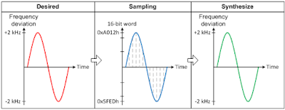
by digitally synthesizing the FM modulation through the PLL. If VCO = N x
RefClk, by continuously changing the N value in a precise manner, you can
synthesize the modulation domain view waveform, as shown in Figure 2. The
advantages of this method are that the frequency deviation does not depend on
Kvco and the VCO frequency anymore. In addition, if the LBW is wide enough, the
modulation frequency response will be flat. The trade-off is that this method
requires higher digital processing power from the logics because the PLL
requires continuous programming. Plus, the synthesizing rate (or sampling rate)
must be higher than the modulation frequency in order to reduce the sidebands
created from sampling. For more details on this method, see the application
report, “Frequency Shift Keying with LMX2571.”
Figure 4 shows how the desired waveform is sampled and synthesized with LMX2571.
Figure 4: Digital implementation technique
Which technique is better?
In analog FM radio broadcasting system, the analog
technique will be better. It is because the carrier is usually fixed at a
particular frequency. The shortcomings of this technique do not happen at all.
In applications with multiple carrier channels, for
example, 2-way radio, the digital technique will be superior to the analog
technique.
In general, both techniques have their pros and cons. The
adoption will depend on the application needs, system capability, performance
index, and cost.
Established in 2000, the Soukacatv.com main
products are modulators both in analog and digital ones, amplifier and
combiner. We are the very first one in manufacturing the headend system in
China. Our 16 in 1 and 24 in 1 now are the most popular products all over the
world.
For more, please access to
https://www.soukacatv.com.
CONTACT US
Dingshengwei Electronics Co., Ltd
Company Address: Building A, the first industry park of
Guanlong, Xili Town, Nanshan, Shenzhen, Guangdong, China
Tel: +86 0755 26909863
Fax: +86 0755 26984949
Phone: +86 13410066011
Email:ken@soukacatv.com
Skype: soukaken
Source:e2e.ti


没有评论:
发表评论