Modulation Basics
Modulation is a process in which a
modulator changes some attribute of a higher frequency carrier signal
proportional to a lower frequency message signal. If the carrier is represented
by the equation
Figure 1. Carrier Signal Equation
a change in the message signal will produce a corresponding change in either the amplitude, frequency, or phase of the carrier. A transmitter can then send this carrier signal through the communication medium more efficiently than the message signal alone. Finally, a receiver will demodulate the signal, recovering the original message.
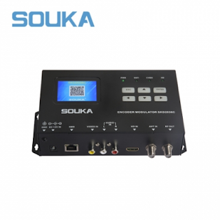
HDMI Encoder Modulator,16in1 Digital
Headend, HD RF Modulator at Soukacatv.com
SKD3013 3 Channel HD Encode Modulator
SKD19 Series 1U Rack 12CH Encode Modulator
In Amplitude Modulation (AM), pictured below, the amplitude of the carrier sinusoid changes based on the amplitude of the message.
Figure 2. Amplitude Modulation
The message signal (red) rides on top of the carrier as the amplitudes of both vary with time. The frequency of the carrier, however, is much higher than the frequency of the message. This carrier frequency is the center of the 'channel,' or frequency allocation of this RF signal. Frequency allocations vary depending on the medium of transmission. For broadcast transmissions, where signals are sent through the air, the government regulates frequency allocation. If the RF signal is transmitted over wire, such as in cable television, there is more freedom in the choice of carrier.
In addition to amplitude modulation, frequency modulation varies the frequency of the carrier sinusoid based on the amplitude of the message signal. Similarly, phase modulation changes the phase of the carrier in response to a change in amplitude of the message.
Digital modulation is similar to analog
modulation, but rather than being able to continuously change the amplitude,
frequency, or phase of the carrier, there are only discrete values of these
attributes that correspond to digital codes. There are several common digital
modulation schemes, each varying separate sets of parameters. The simplest type
is called On Off Keying (OOK) where the amplitude of the
carrier corresponds to one of two digital states. A nonzero amplitude
represents a digital one while a zero amplitude is a digital zero. A specific
implementation of OOK is Morse Code. Frequency Shift Keying (FSK),
seen in Figure 3, is a form of frequency modulation where a certain frequency
represents each binary value.
Figure 3. Frequency Shift Keying (FSK)
Finally, Quadrature Amplitude Modulation (QAM) uses combinations of amplitudes and phases to represent more than 2 digital states, as many as 1024.
I and Q Data
Before comparing IQ and IF modulators, review the tutorial: "What is I/Q Data?".
Before comparing IQ and IF modulators, review the tutorial: "What is I/Q Data?".
I/Q Data in Communication Systems
To explain why I/Q data is used in
communications systems, you must understand modulation basics.
RF communication systems use advanced
forms of modulation to increase the amount of data that can be transmitted in a
given amount of frequency spectrum. Signal modulation can be divided into two
broad categories: analog modulation and digital modulation. Analog or digital refers
to how the data is modulated. If analog audio data is modulated onto a carrier
sine wave, this technology is referred to as analog modulation. If analog audio
data is sampled by an analog-to-digital converter (ADC) with the resulting
digital bits modulated onto a carrier sine wave, this technology is defined as
digital modulation because digital data is encoded. Both analog modulation and
digital modulation involve changing the carrier wave amplitude, frequency, or
phase (or combination of amplitude and phase simultaneously) according to the
message data.
Amplitude modulation (AM), frequency
modulation (FM), or phase modulation (PM) are all examples of analog
modulation. With amplitude modulation, the carrier sine wave amplitude is
modulated according to the message signal. The same idea holds true for
frequency and phase modulation.
Time Domain of AM, FM, and PM Signal
IQ vs. IF Modulators
After calculating digital I and Q data from the baseband message signal, there are two methods of converting this data into an analog RF signal. The first method involves converting I and Q data into analog signals, then feeding them into a quadrature encoder. There, they control the amplitudes of two oscillators, operating 90 degrees out of phase. The output of these oscillators is summed, resulting in an RF signal with the appropriate amplitude, phase, and frequency.
Figure 4. IQ Modulation
The next method of converting digital I and Q data to analog RF performs the oscillator scaling and summing in the digital domain. That is, digital sinusoids with a phase difference of 90 degrees are scaled by the digital I and Q values, then added together. These digital sinusoids are of a lower frequency than the analog oscillators in the IQ modulation scheme, but still at a significantly higher frequency than the message signal. A digital to analog converter (DAC), which operates at a much higher frequency than the DAC used in IQ modulation, converts the resulting digital waveform to low frequency analog RF. Finally, an analog IF to RF up converter uses several stages of mixing and filtering to shift the analog RF signal to the desired RF frequency.
Figure 5. IF Modulation
The NI 5660 RF Vectors Signal Analyzer and the NI 5671 RF Vector Signal Generator use the IF modulation scheme depicted in Figure 5.
Established
in 2000, the Soukacatv.com main products are modulators both in analog and
digital ones, amplifier and combiner. We are the very first one in
manufacturing the headend system in China. Our 16 in 1 and 24 in 1 now are the
most popular products all over the world. For more, please access to
https://www.soukacatv.com.
CONTACT
US
Company:
Dingshengwei Electronics Co., Ltd
Address:
Bldg A, the first industry park of Guanlong, Xili Town, Nanshan, Shenzhen,
Guangdong, China
Tel:
+86 0755 26909863
Fax:
+86 0755 26984949
Mobile:
13410066011
Email:
ken@soukacatv.com
Source:
ni


没有评论:
发表评论