Modulation is the use of one electrical
signal to “control” a primary variable of another. For example, if an audio
signal voltage is used to control the “amplitude” of a carrier signal, the
result is amplitude modulation.
HDMI Encoder Modulator,16in1 Digital Headend,
HD RF Modulator at Soukacatv.com
SKD3013 3 Channel HD Encode Modulator
SKD19 Series 1U Rack 12CH Encode Modulator
It is important that you do not confuse
“mixing” with “modulation.” Mixing occurs when two (or more) signals are simply
combined in a linear network. Modulation, however, requires one signal to
“control” a variable of another; variables such as the amplitude of an RF
signal [amplitude modulation (AM)], the frequency [frequency modulation (FM)],
the pulse width [pulse width modulation (PWM)], the phase [phase modulation
(PM)], or the pulse code [pulse code modulation (PCM)].
SKD121X Encoding & Multiplexing Modulator
Unfortunately, the electronics industry has
traditionally retained many circuit names that are incorrect in this regard.
For instance, when you examine the actual circuit operation of many circuits
labeled as a “mixer/oscillator,” you will discover that it is really a
“modulator/oscillator.”
Strictly speaking, when two signals are
mixed, they combine without the creation of any additional frequencies. When
two signals are modulated, they are said to “beat” with each other, creating
additional frequencies called “beat frequencies.”
If the two modulated signals are sinusoidal,
the beat frequencies will be the sum and the difference of the original
frequencies. AM radio broadcast transmissions contain two signals of primary
importance to the user: the carrier signal and the audio signal, or the program
signal.
The carrier frequency is the frequency to
which the radio receiver is tuned for station selection. For example, the AM
radio band (also referred to as the medium-wave broadcast band, or simply the
broadcast band) is legally designated from 535 to 1605 kHz. If your favorite
local radio station broadcasts on 830 kHz, this means that the carrier
frequency being used for transmission is 830 kHz. The audio signal, or program,
is riding on this carrier frequency.
Figure 1 illustrates an amplitude-modulated wave
shape as it would appear when picked up by a radio antenna. Notice that the
carrier frequency is much higher than the program signal riding on it. In
actuality, there is not a literal program signal “on top of” the carrier.
When the AM signal was broadcast, the program
signal modulated the amplitude, or the level, of the carrier; this process
formed an “envelope” of carrier amplitude, having the same shape as the program
signal. The “beat” frequencies, contained within the AM waveform of Fig. 1,
will be the sum and the difference of the carrier and its program signal.
Examples
For example, if the program signal were a
constant 5-kHz tone, with a carrier frequency of 600 kHz, the beat frequencies
would be 595 kHz (difference frequency) and 605 kHz (sum frequency). In a
typical AM broadcast, the program signal will contain vocal and music
information, making up a very wide range of frequencies. The highest frequency,
of this range of frequencies, will determine the maximum separation of the beat
frequencies from the carrier.
For example, if the highest frequency in the
program signal was limited to 1 kHz, then the beat frequencies would be 599 and
601 kHz. However, as you can see from the earlier example, when the highest
frequency is limited to 5 kHz, the width (or distance from the carrier
frequency) increases. The range of beat frequencies above (and below) the
carrier frequency are called sidebands. The width of the sidebands is closely
monitored at AM broadcast stations because, if they become too wide, they can
interfere with adjacent stations.
Frequency modulation (FM) radio signals also
have a carrier signal and a program signal. However, the program signal does
not ride “on” the carrier frequency; it is contained “within” frequency
variances modulated into the carrier signal.
Because the program signal is not dependent
on carrier amplitudes (as are AM transmissions), FM radio is largely immune to
many forms of interference.
Figure 2 illustrates an exaggeration of an
FM-modulated waveform.
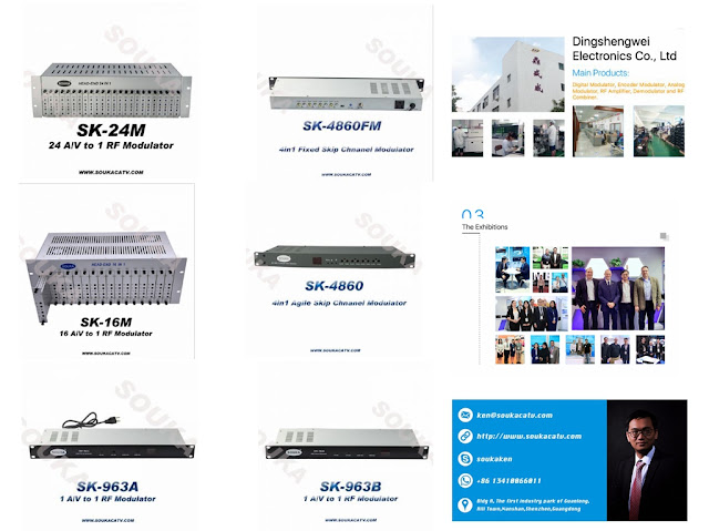
Established in 2000, the Soukacatv.com main
products are modulators both in analog and digital ones, amplifier and
combiner. We are the very first one in manufacturing the headend system in
China. Our 16 in 1 and 24 in 1 now are the most popular products all over the
world.
For more, please access to
https://www.soukacatv.com.
CONTACT US
Company: Dingshengwei Electronics Co., Ltd
Address: Bldg A, the first industry park of
Guanlong, Xili Town, Nanshan, Shenzhen, Guangdong, China
Tel: +86 0755 26909863
Fax: +86 0755 26984949
Mobile: 13410066011
Email: ken@soukacatv.com
Source: electrical-engineering-portal


没有评论:
发表评论